
Bicycle handle mounting member

a technology for mounting parts and bicycles, which is applied in the direction of cycle equipment, steering devices, optical signals, etc., can solve the problems of often having to look at the rider, wires can often be easily torn from the display unit, and wires are often very unsightly

Inactive Publication Date: 2003-07-01
SHIMANO INC
View PDF21 Cites 44 Cited by
  • Summary
  • Abstract
  • Description
  • Claims
  • Application Information

AI Technical Summary

Benefits of technology

One object of the present invention is to provide a bicycle handle mounting member that fixedly secures a handlebar and a display unit in an integrated fashion.
Another object of the present invention is to provide a bicycle handle mounting member in which the wiring between the display unit and the control device or switch is mounted on the handlebar.

Problems solved by technology

Depending upon the function of the display unit, this may result in the rider frequently having to look for the display unit.
Moreover, these display units often have their wires taped or strapped to the handlebars and various frame parts.
These wires can often be inadvertently torn from the display unit.
Moreover, these wires are often very unsightly.

Method used


Image

  • Bicycle handle mounting member
  • Bicycle handle mounting member
  • Bicycle handle mounting member

Examples


first embodiment

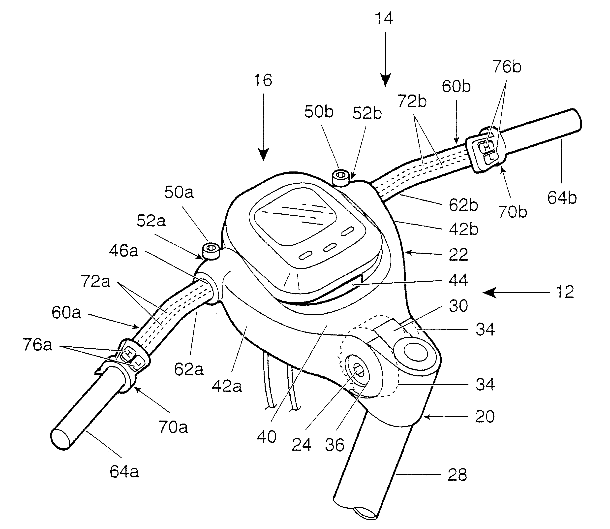
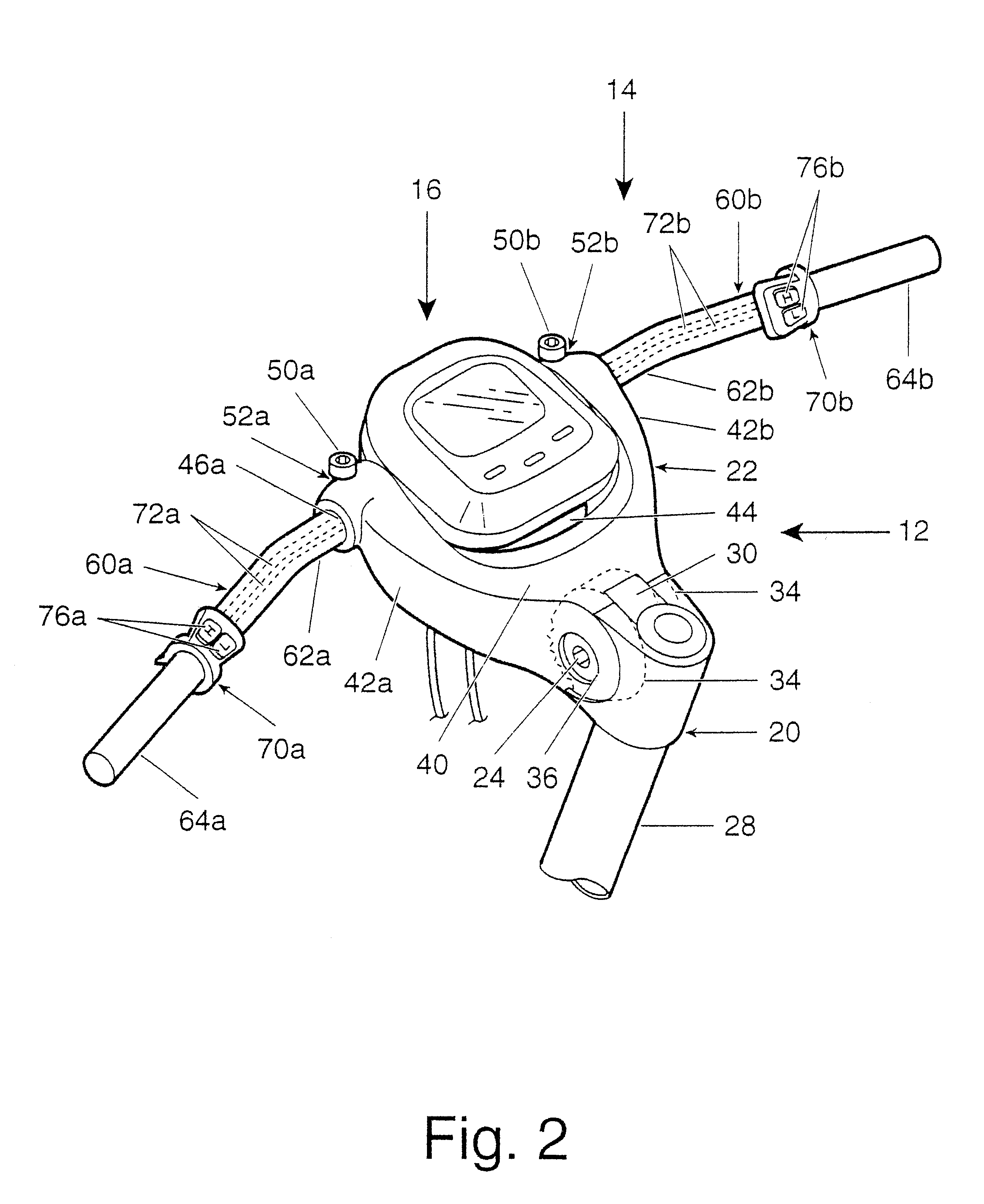
The attachment ends 162a and 162b are clamped in first and second clamping portions 52a and 52b, respectively. The attachment ends 162a and 162b have inner serrated surfaces 166a and 166b. Preferably, the inner serrated surfaces 166a and 166b have substantially truncated cone shapes. These serrated inner surface surfaces 166a and 166b are designed to non-rotatably hold the display unit 16, in the same manner as the

The tubular sections 160a and 160b are provided with openings 168a and 168b that are normally covered by the switches or control devices 70a and 70b. This arrangement allows the display unit 16 to be wired to the switches or control devices 70a and 70b without the wires 72aand 72b being exposed. In other words, the wires 72a and 72b are completely concealed within the interior of tubular sections 160a and 160a between the display unit 16 and the switches or control devices 70a and 70b.

third embodiment

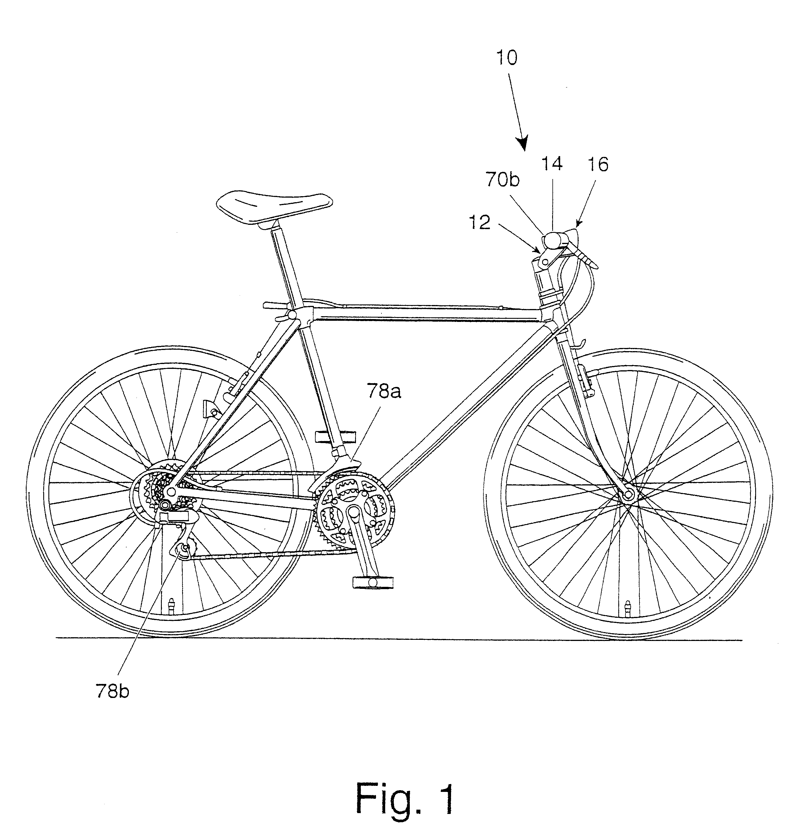
Referring now to FIGS. 6 and 7, a bicycle handle mounting member 212 is illustrated in accordance with a third embodiment of the present invention and adapted to be coupled to bicycle 10 in a conventional manner. This third embodiment has modified mounting structures for supporting the handlebar 214 and the display unit 216. In view of the similarities between this embodiment and the prior embodiment, this embodiment will not be discussed or illustrated in detail herein except to explain the differences between the two embodiments.

In this embodiment, the stem portion 220 is identical to stem portion 20 of the first embodiment, while the handlebar display unit support portion 222 is modified. The handlebar and display unit support portion 222 is modified such that the handlebar 214 and the display unit 216 are mounted in a different manner. More specifically, a separate clamping member 252 is fastened to the base section 240 of the handlebar and display unit support portion 222 via a...


PUM


Abstract

A bicycle handle mounting member is provided for mounting a handlebar and a display unit thereto. The mounting member includes a stem portion configured to be coupled to a bicycle frame and a handlebar and display unit support portion movably coupled to the stem portion. The handlebar and display unit support portion includes a handlebar clamp and first and second mounting flanges. The handlebar clamp has the handlebar fixedly coupled thereto. The first and second mounting flanges are spaced apart to form a display receiving space with the display unit fixedly coupled therebetween. In the preferring embodiments, the handlebar and the display unit are mount to the bicycle handle mounting member such that the wiring between the display unit and control members mounted to the handlebar are completely concealed.

Description

1. Field of the InventionThis invention generally relates to a bicycle handle mounting member. More specifically, the present invention relates a bicycle handle mounting member that fixedly secures a handlebar and a display unit.2. Background InformationBicycling is becoming an increasingly more popular form of recreation as well as a means of transportation. Moreover, bicycling has become a very popular competitive sport for both amateurs and professionals. Whether the bicycle is used for recreation, transportation or competition, the bicycle industry is constantly improving the various components of the bicycle.More specifically, bicycles are being made to be more user friendly and more convenient to operate. One area of the bicycle that is constantly being improved is the controls of the bicycle. The controls are being made to be easier to use, as well as being better designed. For example, bicycle displays are typically mounted on the handlebar as a separate element. These displ...

Claims


Application Information

Patent Timeline
IPC IPC(8): B62K21/00B62J39/00B62K21/12B62J6/16B62J11/19B62J99/00
CPCB62J99/00B62K21/12B62J2099/0026Y10T74/20792Y10T74/20822B62J2099/0033B62M25/08B62K21/125B62J50/225B62J45/20B62J50/22B62J11/19
Inventor KOJIMA, MASAO
Owner SHIMANO INC
Features
  • Generate Ideas
  • Intellectual Property
  • Life Sciences
  • Materials
  • Tech Scout
  • Unparalleled Data Quality
  • Higher Quality Content
  • 60% Fewer Hallucinations
Learn More