Formation testing while drilling apparatus with axially and spirally mounted ports

a technology of axial and spiral mounting and drilling apparatus, which is applied in the direction of survey, fluid removal, borehole/well accessories, etc., can solve the problems of large capital investment required for commercial development of hydrocarbon fields, risk of premature water breakthrough at the producing well, and insufficient information alon

Inactive Publication Date: 2003-07-01
BAKER HUGHES INC
View PDF8 Cites 179 Cited by
  • Summary
  • Abstract
  • Description
  • Claims
  • Application Information

AI Technical Summary

Benefits of technology

While the particular invention as herein shown and disclosed in detail is fully capable of obtaining the objects and providing the advantages hereinbefore stated, it is to be understood that this disclosure is merely illustrative of the presently preferred embodiments of the invention and that no limitations are intended other than as described in the appended claims.

Problems solved by technology

Commercial development of hydrocarbon fields requires significant amounts of capital.
However, this information alone is not necessarily adequate for a decision on whether the hydrocarbons are economically producible.
For example, a highly viscous oil will not flow easily in low permeability conditions and if water injection is to be used to promote production there may be a risk of premature water breakthrough at the producing well.
The relationship between the formation pressure and the response to a pressure disturbance such as a drawdown test is difficult to measure.
Consequently, a drawback of tools such as those described above is the inability to accurately measure the effect on formation pressure caused by the drawdown test.
When a tool is moved to reposition the port, it is difficult to manage the distance between test points with the precision required for a valid measurement.
The continuing drawback of the above described multiple port tools is that the distance between ports is too large for accurate measurement.

Method used


Image

  • Formation testing while drilling apparatus with axially and spirally mounted ports
  • Formation testing while drilling apparatus with axially and spirally mounted ports
  • Formation testing while drilling apparatus with axially and spirally mounted ports

Examples


Embodiment Construction

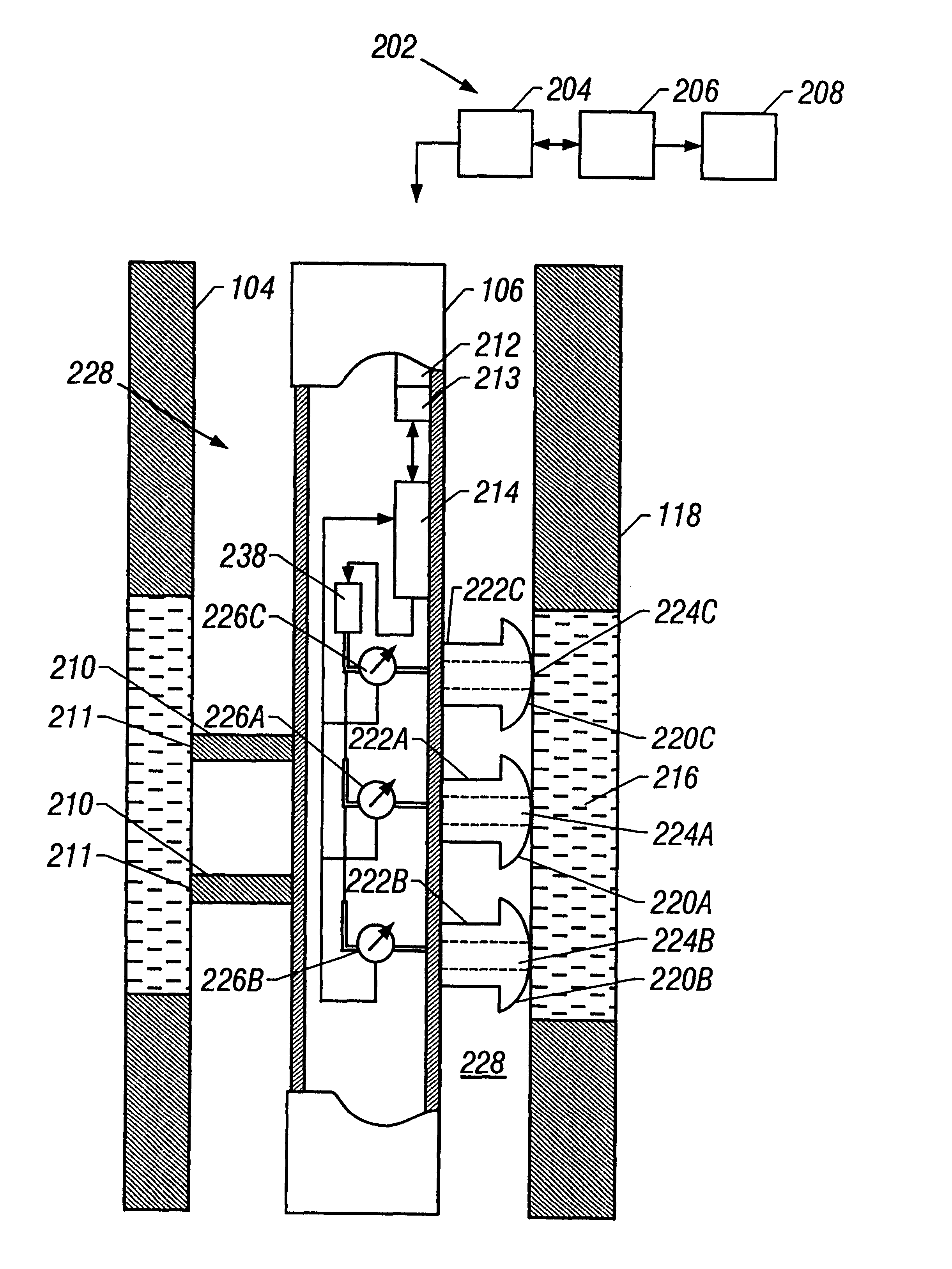
FIG. 1 is a typical drilling rig 102 with a well borehole 104 being drilled into subterranean formations 118, as is well understood by those of ordinary skill in the art. The drilling rig 102 has a work string 106, which in the embodiment shown is a drill string. The drill string 106 has a bottom hole assembly (BHA) 107, and attached thereto is a drill bit 108 for drilling the borehole 104. The present invention is also useful in other drill strings, and it is useful with jointed pipe as well as coiled tubing or other small diameter drill string such as snubbing pipe. The drilling rig 102 is shown positioned on a drilling ship 122 with a riser 124 extending from the drilling ship 122 to the sea floor 120. The present invention may also be adapted for use with land-based drilling rigs.

If applicable, the drill string 106 can have a downhole drill motor 110 for rotating the drill bit 108. Incorporated in the drill string 106 above the drill bit 108 is a typical testing unit, which can ...


PUM


Abstract

An apparatus and method for determining permeability of a subterranean formation is provided. The apparatus and method comprise a work string, at least one selectively extendable member mounted on the work string to isolate a portion of the annular space between the work string and borehole. A predetermined distance proportional to the radius of a control port separates at least two ports in the work string. A sensor operatively associated with each port is mounted in the work string for measuring at least one characteristic such as pressure of the fluid in the isolated section.

Description

1. Field of the InventionThis invention relates to the testing of underground formations or reservoirs and more particularly relates to determining formation pressure and formation permeability.2. Description of the Related ArtTo obtain hydrocarbons such as oil and gas from a subterranean formation, well boreholes are drilled into the formation by rotating a drill bit attached at a drill string end. The borehole extends into the formation to traverse one or more reservoirs containing the hydrocarbons typically termed formation fluid.Commercial development of hydrocarbon fields requires significant amounts of capital. Before field development begins, operators desire to have as much data as possible in order to evaluate the reservoir for commercial viability. Various tests are performed on the formation and fluid, and the tests may be performed in situ. Surface tests may also be performed on formation and fluid samples retrieved from the well.One type of formation test involves produ...

Claims


Application Information

Patent Timeline
Patent Type & Authority Patents(United States)
IPC IPC(8): E21B49/10E21B49/00
CPCE21B49/10
Inventor LEE, JAEDONGMICHAELS, JOHN M.KRUEGER, VOLKERMEISTER, MATTHIASBERGER, PER-ERIK
Owner BAKER HUGHES INC
Why Eureka
Try Eureka