Adjustable depth drill bit

a drill bit and adjustable technology, applied in bone drill guides, medical science, surgery, etc., can solve the problems of small margin of error in spinal surgery, tissue damage, and provide a depth limitation function, and achieve the effect of convenient cleaning and/or sterilization of the tool

Active Publication Date: 2005-10-06
SYNTHES USA
View PDF53 Cites 152 Cited by
  • Summary
  • Abstract
  • Description
  • Claims
  • Application Information

AI Technical Summary

Benefits of technology

[0021] The housing further may comprise proximal and distal housing portions, and the proximal housing may comprise a spring operable to bias the drill in the retracted position. The distal housing may comprise threads for engaging a bone screw hole of the bone plate. The proximal end of the distal housing further may comprise protrusion and recess elements configured to engage respective recess and protrusion elements on the distal end of the proximal housing to rotationally fix the two housings. The housing further may comprise a retainer for removably coupling the proximal and distal housings, such that the proximal and distal housings can be decoupled to facilitate cleaning and / or sterilization of the tool.

Problems solved by technology

More particularly, the device is removably attachable to a bone screw hole of a fixation plate and provides a depth limiting function for precision boring of the bone in precise alignment with the bone screw hole of the bone fixation plate.
The margin for error in spinal surgery is small, particularly because of the sensitivity of the spinal cord and the risk inherent in performing invasive procedures near the spinal cord.
Misalignment of the screw within the screw hole of the plate may increase the risk of tissue damage, bone screw failure, fixation failure, and / or bone screw ‘back-out’ thus increasing the risk of further injury to the patient and defeating the usefulness of the plate.
One drawback of the typical drill guide is that it is yet another piece of surgical equipment that must be separately manipulated and accounted for at the surgical suite.
This often complicates the surgical procedure, increases the chance for error, and increases the length of surgical procedure.
Yet another consideration is the amount of injury that may result if the drilling procedure and or bone screw penetrate beyond a particular depth.
For example, the injury that may result from a misplaced, mis-angled, or misjudged penetration depth of a bone screw placed into a vertebra often can be drastic and permanent.

Method used


Image

  • Adjustable depth drill bit
  • Adjustable depth drill bit
  • Adjustable depth drill bit

Examples


Embodiment Construction

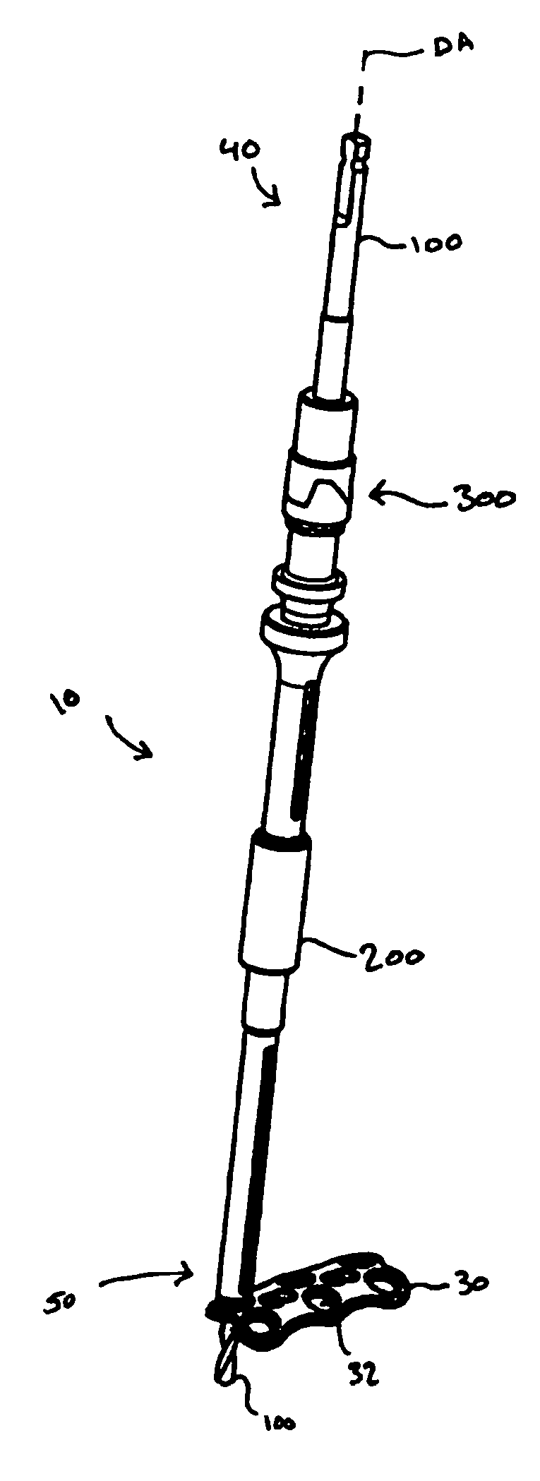
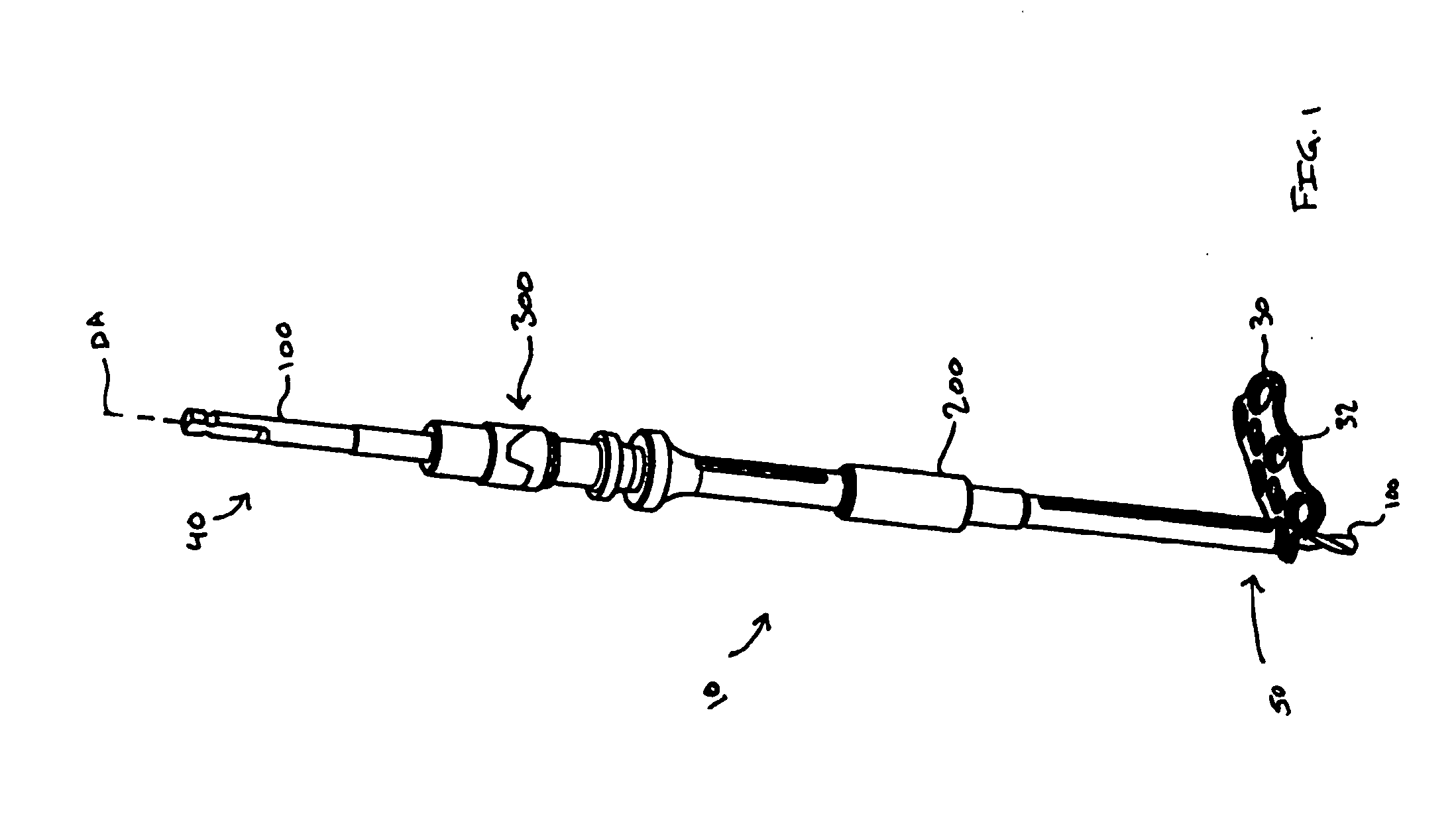
[0048] Referring to FIG. 1, there is shown an exemplary drill assembly 10, which may be adapted for use with a fixation device, such as for example, a spinal fixation plate 30. While the drill assembly is disclosed in conjunction with a spinal fixation plate it is contemplated that the drill assembly may be used in conjunction with bone fixation plates used on or in any portion of the body. The drill assembly may be used with metal fixation plates as well as with bio-resorbable, polymer based, or any other bone fixation plates known in the art. Drill assembly 10 may include a drill bit 100 having a proximal end 40, a distal end 50 and a longitudinal axis 20. Drill assembly 10 also may include a housing assembly 200, and an adjustable depth stop assembly 300 each disposed along the length of the drill bit 100. The housing assembly 200 may be configured to orient and fix the drill bit with respect to the bone plate and bone (i.e. it may fix the drill trajectory), while the adjustable ...


PUM


Abstract

A drill guide with integral drill bit is provided for drilling a hole into bone. The drill guide may have a housing for engaging a screw hole of a bone plate to fix the trajectory of the drill guide and drill with respect to the bone plate. An adjustable stop assembly is also provided and is axially slidable along the drill bit. The adjustable stop has a drill bit engaging mechanism to selectively lock the adjustable stop to the drill bit at a desired location to limit the depth that the drill may penetrate into the bone.

Description

FIELD OF THE INVENTION [0001] The present invention relates to a device for boring a hole into a bone. More particularly, the device is removably attachable to a bone screw hole of a fixation plate and provides a depth limiting function for precision boring of the bone in precise alignment with the bone screw hole of the bone fixation plate. BACKGROUND [0002] The use of surgical fixation plates for a variety of orthopaedic applications is a widely accepted. Fixation plates are used by surgeons to stabilize, mend, or align fractured or diseased bones as well as to apply compression or tension to bones and to fuse joints between two or more bones. Typically, fixation plates are fastened to the bone with at least one, and often a plurality, of fasteners such as bone screws that are installed through bone screw holes in the plate. Proper orientation and alignment of the fasteners with the bone plate and secure fixation of the bone plate to the bone can mitigate potential complications a...

Claims


Application Information

Patent Timeline
Patent Type & Authority Applications(United States)
IPC IPC(8): A61B19/00A61B17/32A61B17/16A61B17/17
CPCA61B17/1617A61B17/1728A61B17/1757A61B2090/036A61B2090/062A61B17/16A61B17/32
Inventor RYAN, CHRISTOPHER J.
Owner SYNTHES USA
Why Eureka
Try Eureka