Drillout bi-center bit

Inactive Publication Date: 2002-05-28
CAMCO INT
View PDF35 Cites 155 Cited by
  • Summary
  • Abstract
  • Description
  • Claims
  • Application Information

AI Technical Summary

Problems solved by technology

These attempts often resulted in heavy damage to both the casing and the bi-center drill bit.
The casing tends to be damaged by the gauge cutting elements mounted on the bi-center drill bit because inside the casing the pilot section of the bit is forced to orbit about its center, causing the gauge cutters to engage the casing.
The forced orbiting action of the pilot section also causes damage to the cutters on the leading face of the bi-center dr

Method used


Image

  • Drillout bi-center bit
  • Drillout bi-center bit
  • Drillout bi-center bit

Examples


Embodiment Construction

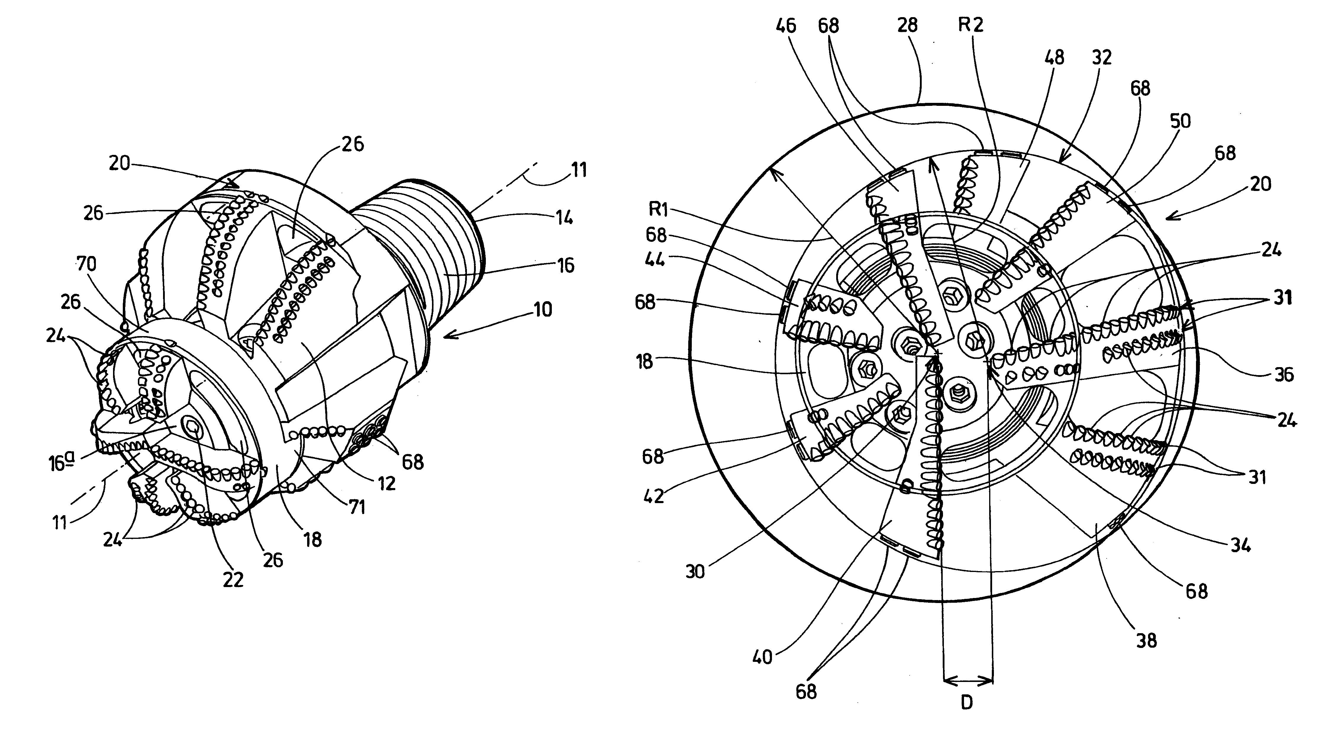
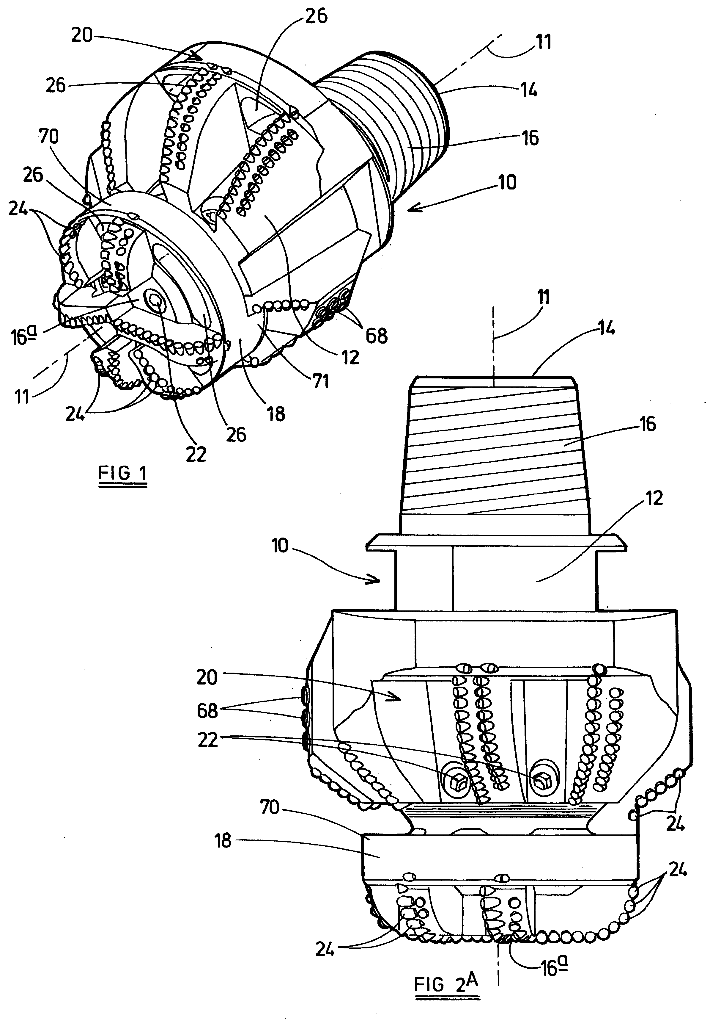
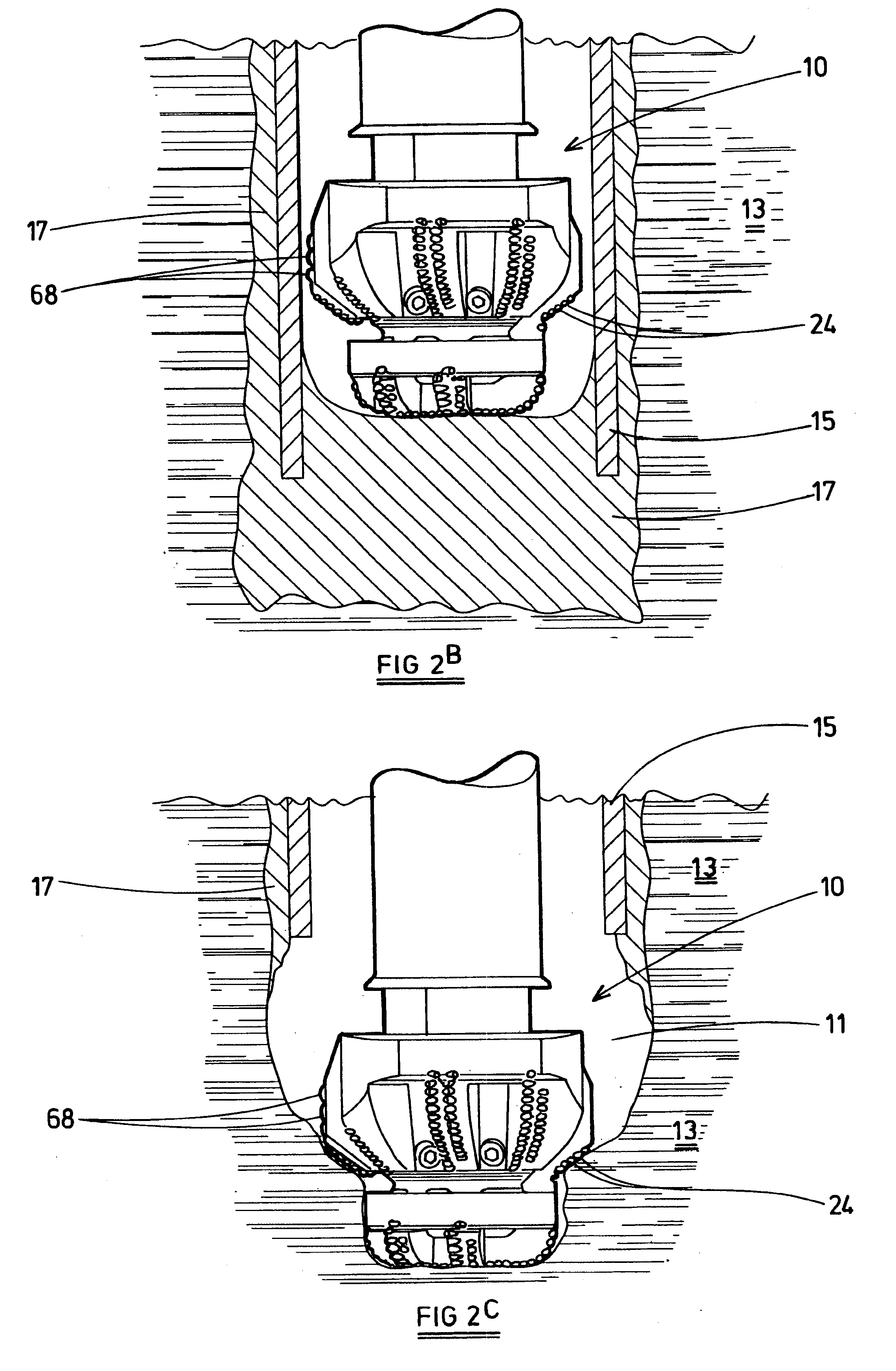
As shown in FIGS. 1 and 2A, the bi-center drill bit 10 of the present invention has a longitudinal axis 11, a bit body 12 with a first end 14 which is adapted to be secured to a drill string (not shown). Typically, threads 16 are used for attachment to the drill string, but other forms of attachment may also be utilized. At the second, opposite end 16 of the bit body 12 is the pilot section 18 of the bi-center drill bit 10. A reamer section, shown generally by numeral 20, is intermediate the first end 14 and the pilot section 18 of the bi-center drill bit 10.

During operation, the bit body 12 is rotated by an external means while the bi-center drill bit 10 is forced into the material being drilled. The rotation under load causes cutting elements 24 to penetrate into the drilled material and remove the material in a scraping and / or gouging action.

The bit body 12 has internal passaging (not shown) with allows pressurized drilling fluid to be supplied from the surface to a plurality of ...


PUM


Abstract

The present invention is a bi-center drill bit designed to drill out the cement and other material in the casing and then proceed to drill out the full gauge drilling diameter borehole with a diameter greater than the inside of the casing. The bi-center drill bit is configured with non-drilling bearing elements that contact with the casing when the bit is drilling the cement without allowing the gauge cutting elements of the bi-center drill bit to contact the casing. The bi-center drill bit also has a cutting element configuration which prevents reverse scraping of the cutting elements when drilling both the cement and the formation.

Description

1. Field of the InventionThis invention relates to bits used for drilling boreholes into the earth for mineral recovery. In particular, the present invention is a bi-center drill bit that can drill a borehole in the earth with a diameter greater than that of the drill bit, and also drill out the cement and float shoe after the casing has been cemented in place.2. Description of the Related ArtIn the pursuit of drilling boreholes into the earth for the recovery of minerals, there are instances when it is desirable to drill a borehole with a diameter larger than the bit itself. Drill bits used to form these boreholes are generally known as bi-center type drill bits.Bi-center drill bits are well known in the drilling industry. Various types of bi-center drill bits are described in U.S. Pat. Nos. 1,587,266, 1,758,773, 2,074,951, 2,953,354, 3,367,430, 4,408,669, 4,440,244, 4,635,738, 5,040,621, 5,052,503, 5,165,494, 5,678,644 all herein incorporated by reference, and European Patent Appl...

Claims


Application Information

Patent Timeline
IPC IPC(8): E21B7/06E21B7/04E21B10/00E21B10/26E21B10/42E21B10/43
CPCE21B7/067E21B10/43E21B10/26E21B10/265
Inventor WATSON, GRAHAM R.HART, STEVEN JAMES
Owner CAMCO INT
Why Eureka
Try Eureka