LNG production in cryogenic natural gas processing plants

a technology of cryogenic natural gas and processing plants, which is applied in the direction of gaseous fuels, liquefaction, lighting and heating apparatus, etc., can solve the problems of reducing the purity (i.e. methane concentration) of lng products, reducing the value of liquid products for the plant operator, and affecting the quality of the liquid produ

Inactive Publication Date: 2003-03-04
ORTLOFF ENGINEERS
View PDF37 Cites 147 Cited by
  • Summary
  • Abstract
  • Description
  • Claims
  • Application Information

AI Technical Summary

Problems solved by technology

Although there are many different processes that can be used for carbon dioxide removal, many of them will cause the treated gas stream to become partially or completely saturated with water.
Since water in the feed stream would also lead to freezing problems in the LNG production section, it is very likely that the carbon dioxide removal section 50 must also include dehydration of the gas stream after treating.
Consequently, all of the heavier hydrocarbons present in the feed gas become part of the LNG product, reducing the purity (i.e. methane concentration) of the LNG product.
Unfortunately, this means that the C.sub.2 components, C.sub....

Method used


Image

  • LNG production in cryogenic natural gas processing plants
  • LNG production in cryogenic natural gas processing plants
  • LNG production in cryogenic natural gas processing plants

Examples


example 2

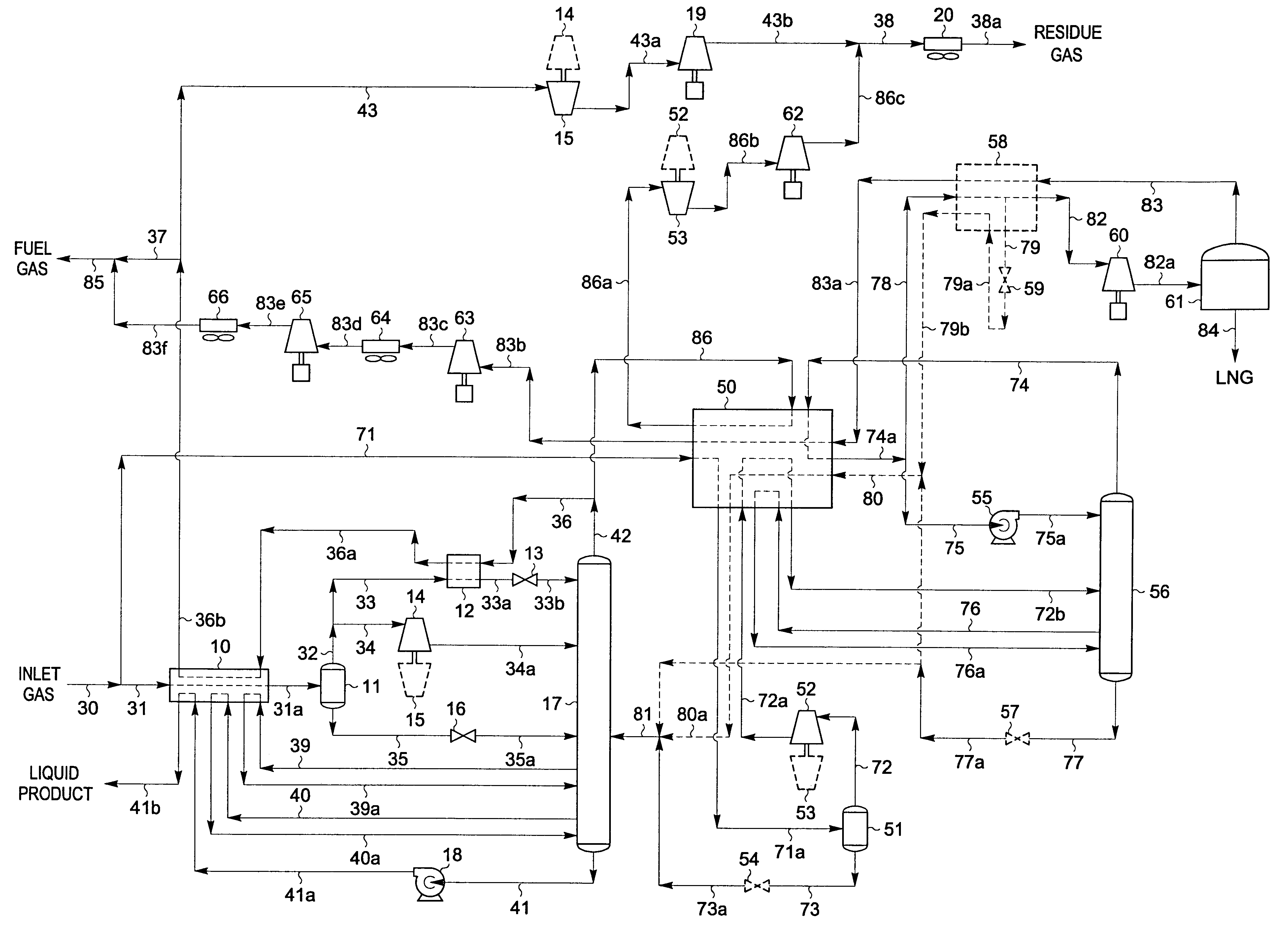
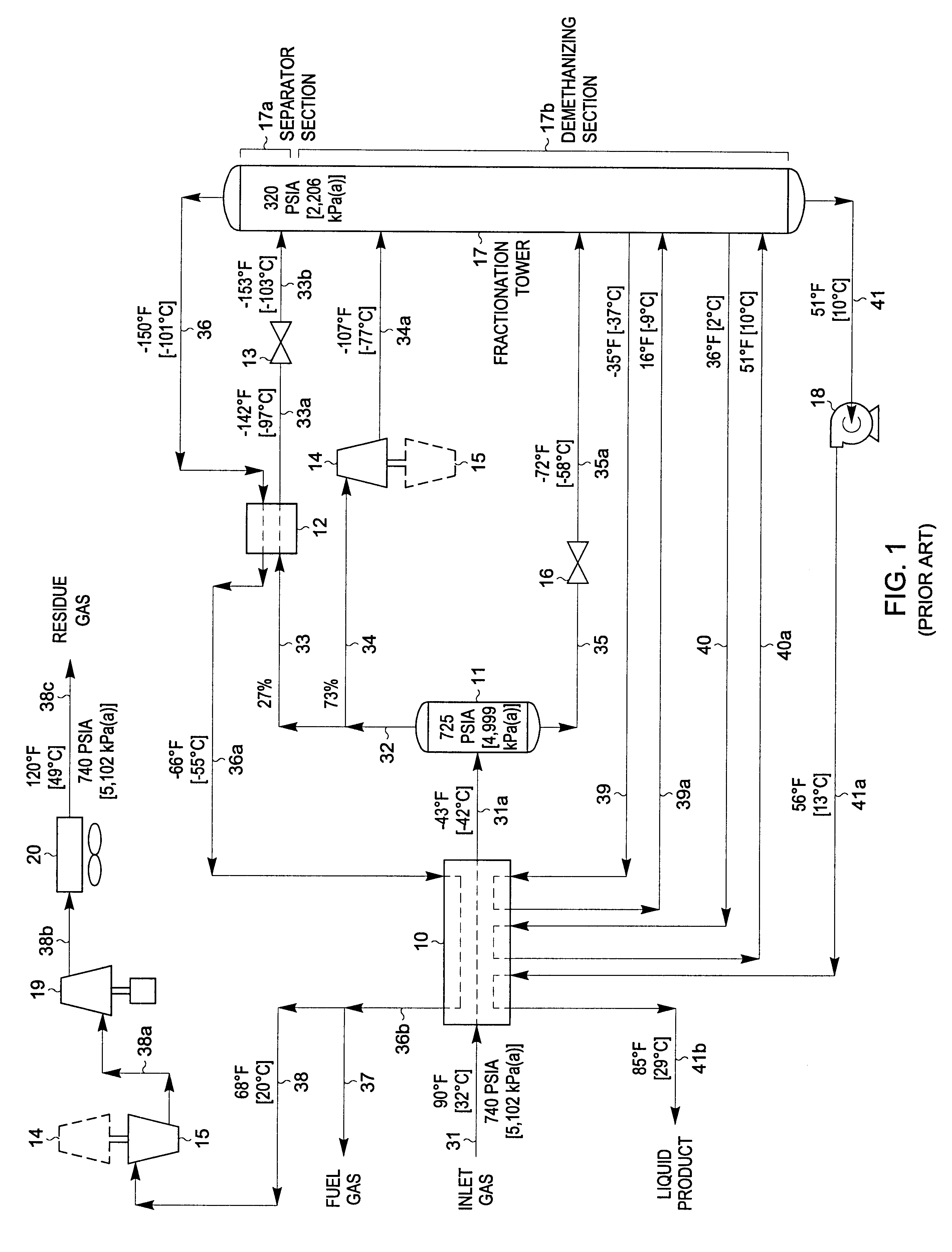
FIG. 4 represents the preferred embodiment of the present invention for the temperature and pressure conditions shown because it typically provides the most efficient LNG production. A slightly less complex design that maintains the same LNG production with somewhat higher utility consumption can be achieved using another embodiment of the present invention as illustrated in the FIG. 5 process. The inlet gas composition and conditions considered in the process presented in FIG. 5 are the same as those in FIGS. 1 through 4. Accordingly, the FIG. 5 process can be compared with that of the FIG. 2 and FIG. 3 processes to illustrate the advantages of the present invention, and can likewise be compared to the embodiment displayed in FIG. 4.

In the simulation of the FIG. 5 process, the inlet gas cooling, separation, and expansion scheme for the NGL recovery plant is essentially the same as that used in FIG. 4. Inlet gas enters the plant at 90.degree. F. [32.degree. C.] and 740 psia [5,102 k...

example 3

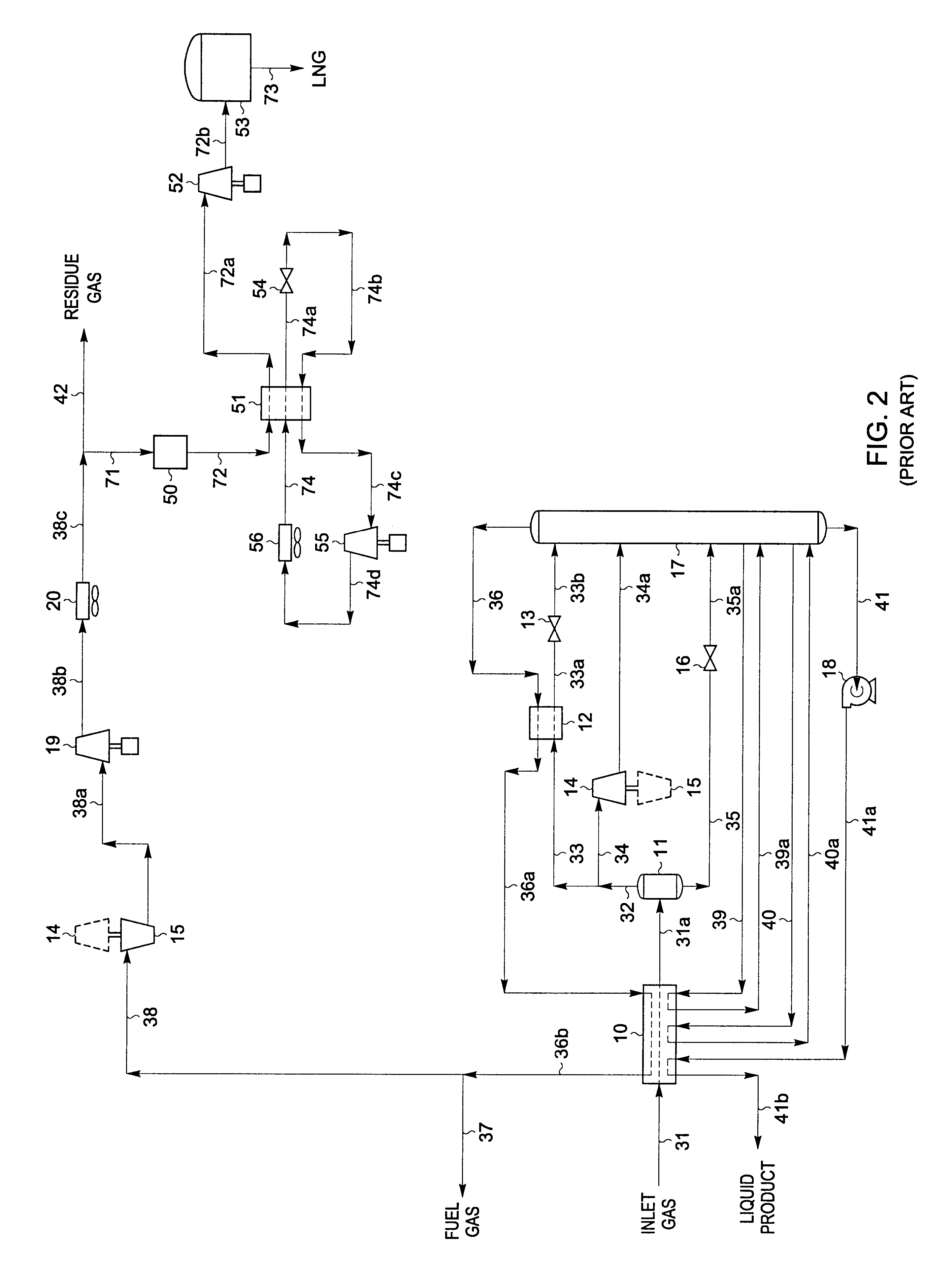
In FIGS. 4 and 5, a portion of the plant inlet gas is processed using the present invention to co-produce LNG. Alternatively, the present invention can instead be adapted to process a portion of the plant residue gas to co-produce LNG as illustrated in FIG. 6. The inlet gas composition and conditions considered in the process presented in FIG. 6 are the same as those in FIGS. 1 through 5. Accordingly, the FIG. 6 process can be compared with that of the FIG. 2 and FIG. 3 processes to illustrate the advantages of the present invention, and can likewise be compared to the embodiments displayed in FIGS. 4 and 5.

In the simulation of the FIG. 6 process, the inlet gas cooling, separation, and expansion scheme for the NGL recovery plant is essentially the same as that used in FIG. 1. The main differences are in the disposition of the cold distillation stream (stream 42) and the compressed and cooled third residue gas (stream 44a) produced by the NGL recovery plant. Note that the third resid...


PUM


Abstract

A process for liquefying natural gas in conjunction with processing natural gas to recover natural gas liquids (NGL) is disclosed. In the process, the natural gas stream to be liquefied is taken from one of the streams in the NGL recovery plant and cooled under pressure to condense it. A distillation stream is withdrawn from the NGL recovery plant to provide some of the cooling required to condense the natural gas stream. The condensed natural gas stream is expanded to an intermediate pressure and supplied to a mid-column feed point on a distillation column. The bottom product from this distillation column preferentially contains the majority of any hydrocarbons heavier than methane that would otherwise reduce the purity of the liquefied natural gas, and is routed to the NGL recovery plant so that these heavier hydrocarbons can be recovered in the NGL product. The overhead vapor from the distillation column is cooled and condensed, and a portion of the condensed stream is supplied to a top feed point on the distillation column to serve as reflux. A second portion of the condensed stream is expanded to low pressure to form the liquefied natural gas stream.

Description

This invention relates to a process for processing natural gas to produce liquefied natural gas (LNG) that has a high methane purity. In particular, this invention is well suited to co-production of LNG by integration into natural gas processing plants that recover natural gas liquids (NGL) and / or liquefied petroleum gas (LPG) using a cryogenic process.Natural gas is typically recovered from wells drilled into underground reservoirs. It usually has a major proportion of methane, i.e., methane comprises at least 50 mole percent of the gas. Depending on the particular underground reservoir, the natural gas also contains relatively lesser amounts of heavier hydrocarbons such as ethane, propane, butanes, pentanes and the like, as well as water, hydrogen, nitrogen, carbon dioxide, and other gases.Most natural gas is handled in gaseous form. The most common means for transporting natural gas from the wellhead to gas processing plants and thence to the natural gas consumers is in high pres...

Claims


Application Information

Patent Timeline
IPC IPC(8): F25J1/00F25J3/02F25J1/02C10L3/06C10L10/14
CPCF25J1/0201F25J3/0209F25J3/0233F25J3/0238F25J3/0242F25J1/0022F25J1/0035F25J1/004F25J1/0042F25J1/0229F25J2260/20F25J2200/04F25J2200/70F25J2200/72F25J2205/04F25J2210/06F25J2220/60F25J2220/62F25J2220/66F25J2230/60F25J2235/60F25J2240/02F25J2240/30F25J2240/40F25J2245/02F25J2270/02F25J2270/90F25J2290/12F25J2290/62F25J2215/04
Inventor CAMPBELL, ROY E.WILKINSON, JOHN D.HUDSON, HANK M.CUELLAR, KYLE T.
Owner ORTLOFF ENGINEERS
Why Eureka
Try Eureka