
Inline pilot with flame detection device and method thereof

a flame detection and pilot technology, applied in the direction of burners, combustion types, combustion regulation, etc., can solve the problems of pilot failures of existing pilot systems, low accuracy or sensitivity of flame detection, and rectification systems, so as to improve flame anchoring, improve flame durability and anchoring, and improve pilot safety

Active Publication Date: 2018-10-16
PROFIRE ENERGY
View PDF3 Cites 12 Cited by
  • Summary
  • Abstract
  • Description
  • Claims
  • Application Information

AI Technical Summary

Benefits of technology

The patent describes a new method for detecting flames using a plurality of parallel tubular-shaped flames. These flames are positioned close to a flame sensor electrode within a pilot nozzle, which allows for improved contact with the flame ions. The nozzle also includes a diffuser that stabilizes the pilot flame and improves flame anchoring. The method and nozzle assembly provide better flame detection and durability.

Problems solved by technology

One of the challenges with flame rectification systems currently used in the industry is low accuracy or sensitivity when detecting flames in harsh environmental conditions or under low combustion conditions.
Also, pilot failures frequently occur in existing pilot systems due to improperly adjusted or loose externally mounted ignition and flame rods that are subjected to extremes in temperature and vibration.
Wind and other environmental factors can shift the flame away from the flames' sensor rod or nozzle to prevent efficient flame detection and may also extinguish the flame.
Also, within enclosed combustion applications, difficult environments inside of the firing enclosure can cause the pilot flame to be diverted away from the flame sensing rod causing premature shutdown, or may be extinguished altogether.
However, these attempts have been inadequate and pilot systems currently available in the industry may prematurely shut down when fuel pressure is low due to adverse environmental events such as icing or clogging and thus may be less reliable under adverse environmental conditions.
Moreover, pilot systems attempting to overcome these issues are very expensive and the majority of pilots used in the industry continue to include externally configured flame sensor electrodes and ground electrodes.

Method used


Image

  • Inline pilot with flame detection device and method thereof
  • Inline pilot with flame detection device and method thereof
  • Inline pilot with flame detection device and method thereof

Examples


Embodiment Construction

[0041]The invention and accompanying drawings will now be discussed so as to enable one skilled in the art to practice the present invention. The drawings and descriptions are exemplary of various aspects of the invention and are not intended to narrow the scope of the appended claims.

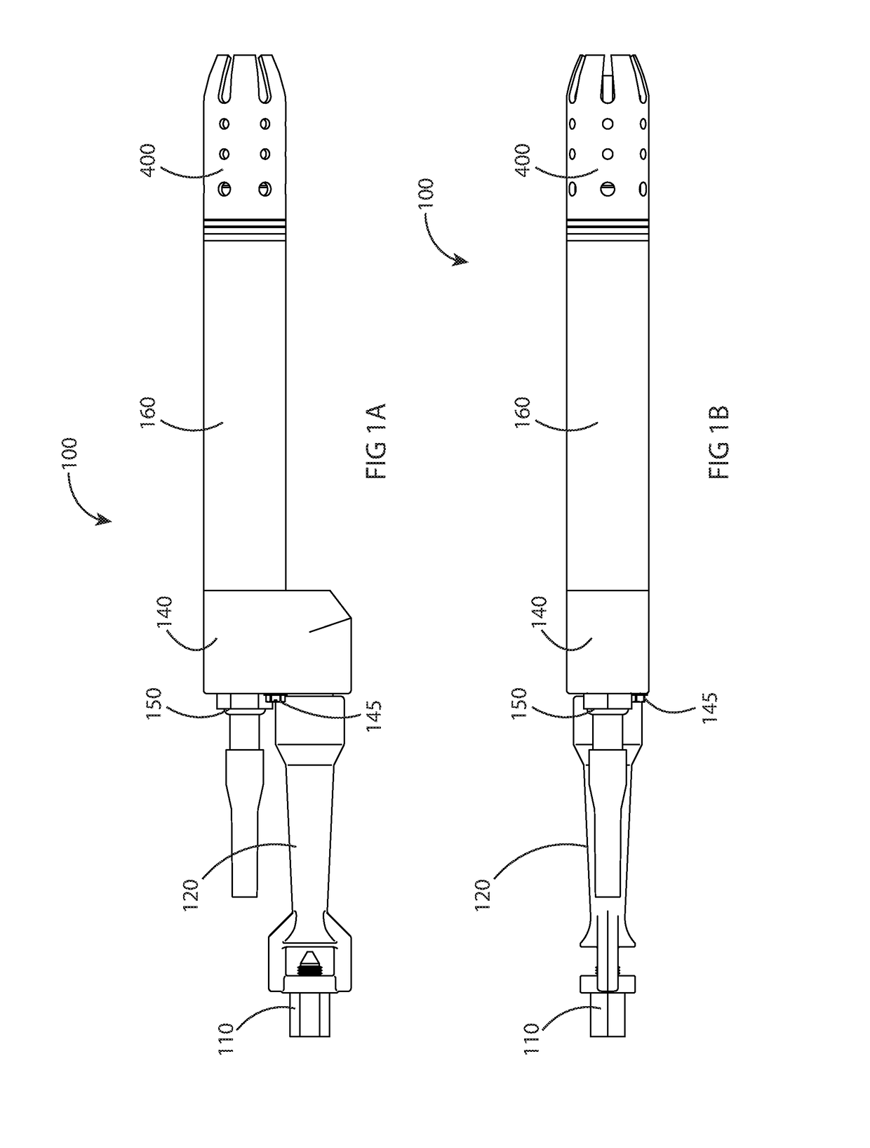
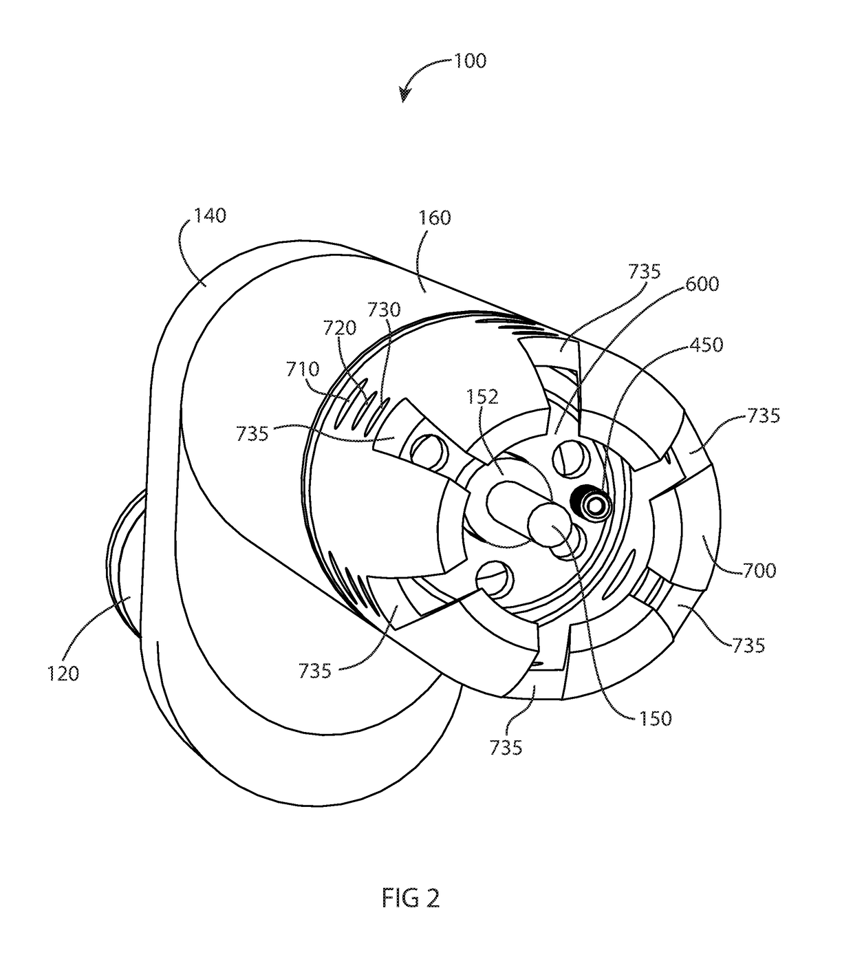
[0042]Turning now to FIGS. 1A-1B, 2, and 3, a novel naturally aspirated inline pilot assembly configured for flame detection is provided in accordance with one or more aspects of the present invention. The inline pilot may include a novel near field ionization method of flame detection in accordance with or more aspects of the present invention. The inline pilot assembly 100 can include a pilot nozzle assembly 400, a pilot spacer tube 160, pilot base hub 140, an axially disposed flame sensor electrode 150, a fuel mixer 120, and a fuel orifice 110. As can be seen from the Figures, the inline pilot may be assembled by connecting the fuel orifice 110 to the pilot mixer 120 at a fuel inlet end of the pilot...


PUM


Abstract

A novel inline pilot assembly and method of flame detection for use with combustion applications for oil or gas processing is provided wherein the pilot assembly includes a pilot novel assembly with a unique placement of fuel and induction holes to improve flame stability, promote flame anchoring near the diffuser, and discourage the pilot flame front from migrating forward away from the diffuser.

Description

PRIORITY[0001]The present application claims the benefit of U.S. Provisional Patent Application Ser. No. 62 / 104,809 filed on Jan. 18, 2015, which is incorporated herein by reference in its entirety.THE FIELD OF THE INVENTION[0002]The present invention relates to pilots having a flame detection device and methods for flame detection. More specifically, the present invention relates to a naturally aspirated inline pilot having a flame detection device for combustion applications for oil and gas processing and a novel method of flame detection using novel near field ionization flame detection.BACKGROUND[0003]Pilots are commonly used for combustion applications for oil and gas processing, including burner management systems, flare stacks, process vessels, separators, boilers, line heaters and other burner applications for oil and gas processing. These pilots typically serve as an ignition source for a larger primary gas burner.[0004]Pilot operation is critical because it impacts the eff...

Claims


Application Information

Patent Timeline
Patent Type & Authority Patents(United States)
IPC IPC(8): F23Q9/00F23N5/02F23D14/08F23N5/12
CPCF23Q9/00F23D14/08F23N5/12F23N5/02F23D2207/00
Inventor LOVELESS, MARK R.PARKS, MELVIN HALHATCH, JUSTIN WPITCHER, STEPHEN N.
Owner PROFIRE ENERGY
Learn More