Redundant level measurement in radar level gauging system

a level measurement and radar technology, applied in the field to achieve the effect of improving the robustness of radar level gauging

Active Publication Date: 2007-08-23
ROSEMOUNT TANK RADAR
View PDF18 Cites 29 Cited by
  • Summary
  • Abstract
  • Description
  • Claims
  • Application Information

AI Technical Summary

Benefits of technology

[0005] An object of the present invention is to overcome the above problems, and to provide a redundant level value in a radar level gauge. According to one embodiment, the redundant level value can be used to improve the robustness of the radar level gauging.

Problems solved by technology

Such reflections may result from internal tank geometry such as flanges, stirring devices, filling nozzles, etc, or from physical properties of the product, such as turbulence, foam, etc.
Such a failure can be e.g. a mechanical or electrical fault in the gauge.

Method used


Image

  • Redundant level measurement in radar level gauging system
  • Redundant level measurement in radar level gauging system
  • Redundant level measurement in radar level gauging system

Examples


Embodiment Construction

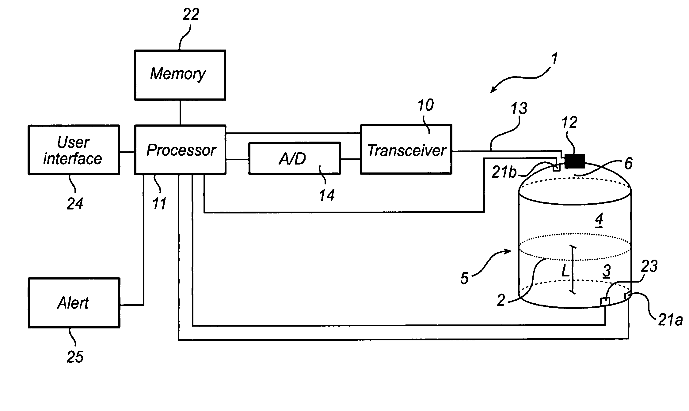
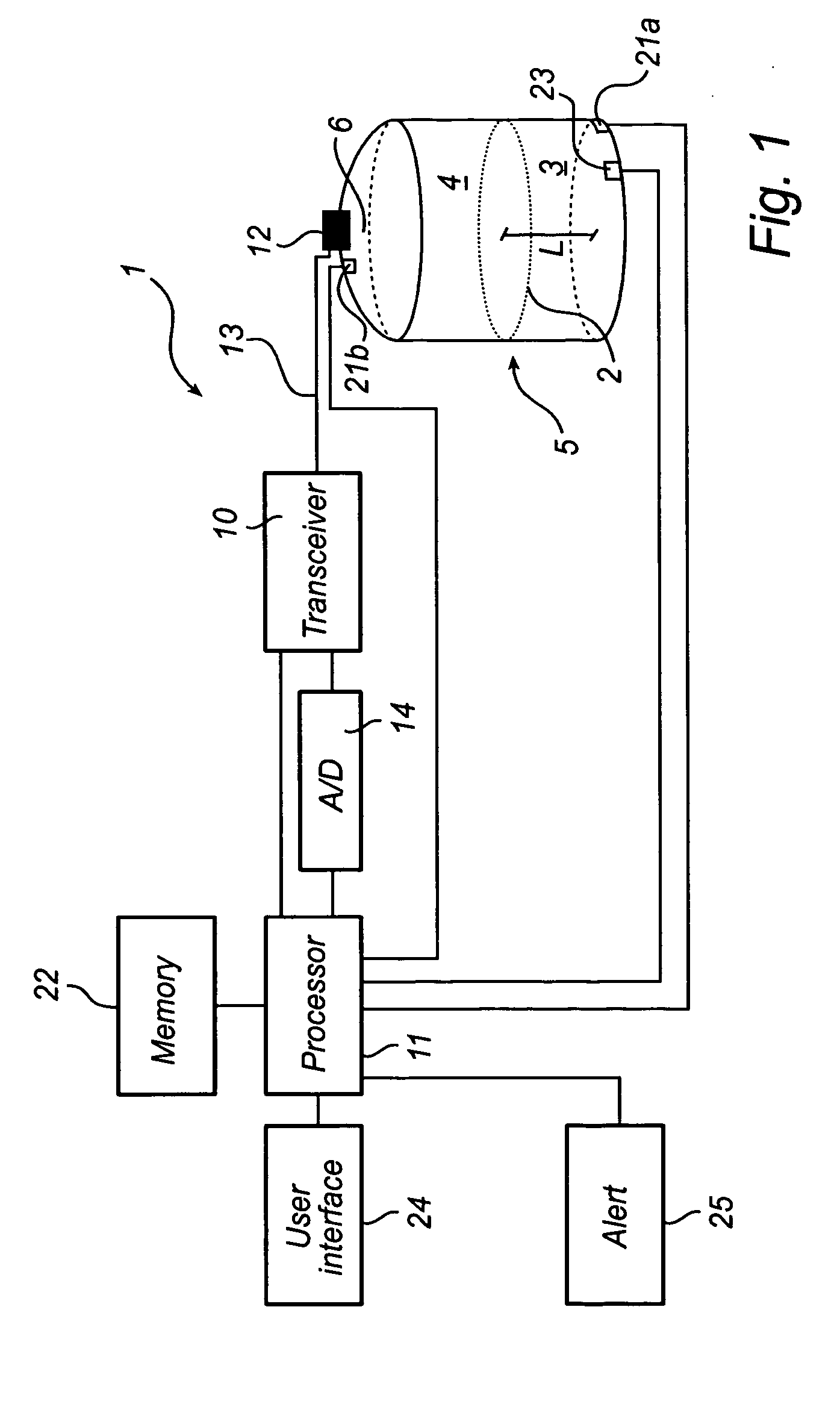
[0022]FIG. 1 schematically shows a radar level gauge (RLG) system 1 according to an embodiment of the present invention.

[0023] The RLG 1 is arranged to determine a product level in a tank, i.e. the level of an interface 2 between two (or more) materials 3, 4 in the tank 5. Typically, the first material 3 is a product stored in the tank, e.g. a liquid such as gasoline, while the second material 4 is air or some other atmosphere. In that case, the RLG will enable detection of the level of the surface of the product in the tank. Typically, only the level of a first liquid surface is measured, and / or a second liquid surface if the first liquid is sufficiently transparent.

[0024] The RLG 1 comprises a transceiver 10, controlled by a processor 11, a signal medium interface 12, and a signal transfer medium 13 connecting the transceiver 10 to the signal medium interface 12. The transceiver 10 is arranged to provide electromagnetic signals to the signal medium interface 12 and to receive a ...


PUM


Abstract

A method and system for determining a product level in a tank, comprising determining a first level measure using emission of electromagnetic waves into the tank, detecting a differential pressure, determining an observed density based on the detected differential pressure and the first level measure, and determining a second level measure based on the observed density and a currently measured differential pressure. The present invention is based on the realization that a level measurement based on differential pressure and an observed density can provide a valuable redundant level measurement. Such a redundant measurement can provide increased reliability and enable detection of errors.

Description

FIELD OF THE INVENTION [0001] The present invention relates to radar level gauging, i.e. using electromagnetic waves for determining a level of a product in a tank. More specifically, the invention relates to determining a redundant level measure that can be used to improve the performance of a radar level gauge (RLG). BACKGROUND OF THE INVENTION [0002] Radar level gauging is based on allowing electromagnetic waves propagate into a tank and be reflected by the surface of a product in the tank. The reflected signal is then received and processed in order to identify an echo, i.e. the reflection from the surface. In order to be accurate, it is important that the surface echo can be distinguished from other disturbing reflections. Such reflections may result from internal tank geometry such as flanges, stirring devices, filling nozzles, etc, or from physical properties of the product, such as turbulence, foam, etc. [0003] Considerable effort is made to ensure that the algorithm used to...

Claims


Application Information

Patent Timeline
Patent Type & Authority Applications(United States)
IPC IPC(8): G01S13/08
CPCG01F23/18G01S13/08G01F25/0061G01F23/284G01F25/20
Inventor HAGG, LENNARTLARSSON, LARS OVEKLEMAN, MIKAELHOLMBERG, PER
Owner ROSEMOUNT TANK RADAR
Why Eureka
Try Eureka