Natural gas processing method

a processing method and natural gas technology, applied in the direction of liquefaction, lighting and heating equipment, solidification, etc., can solve the problems of high equipment cost of a liquefying plant for producing lng, no known instance in which all three types of products are produced from the same plant, and complex equipment configuration, etc., to achieve the effect of low cos

Inactive Publication Date: 2008-07-10
JGC CORP
View PDF4 Cites 11 Cited by
  • Summary
  • Abstract
  • Description
  • Claims
  • Application Information

AI Technical Summary

Benefits of technology

[0029]By the natural gas processing method according to the invention, in a case where the natural gas liquid and the sales gas can be produced as the major products and th

Problems solved by technology

However, there is no known instance in which all the three types of products are produced from the same plant.
The equipment cost of a liquefying plant for producing LNG is expensive.
However, the equipment configuration is complex and cost required to construct the natural gas processing plant is

Method used


Image

  • Natural gas processing method
  • Natural gas processing method
  • Natural gas processing method

Examples


first embodiment

(1) FIRST EMBODIMENT

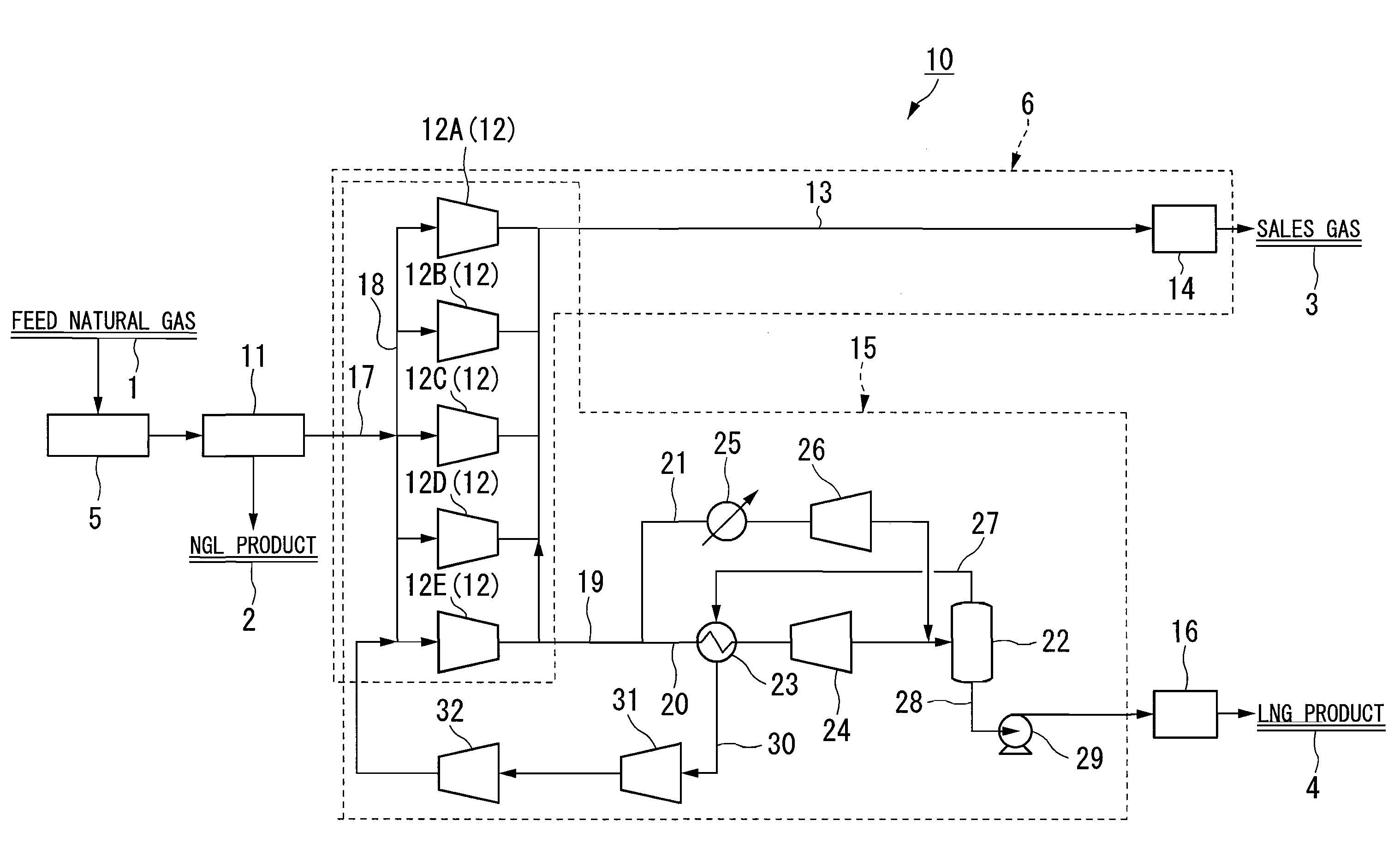
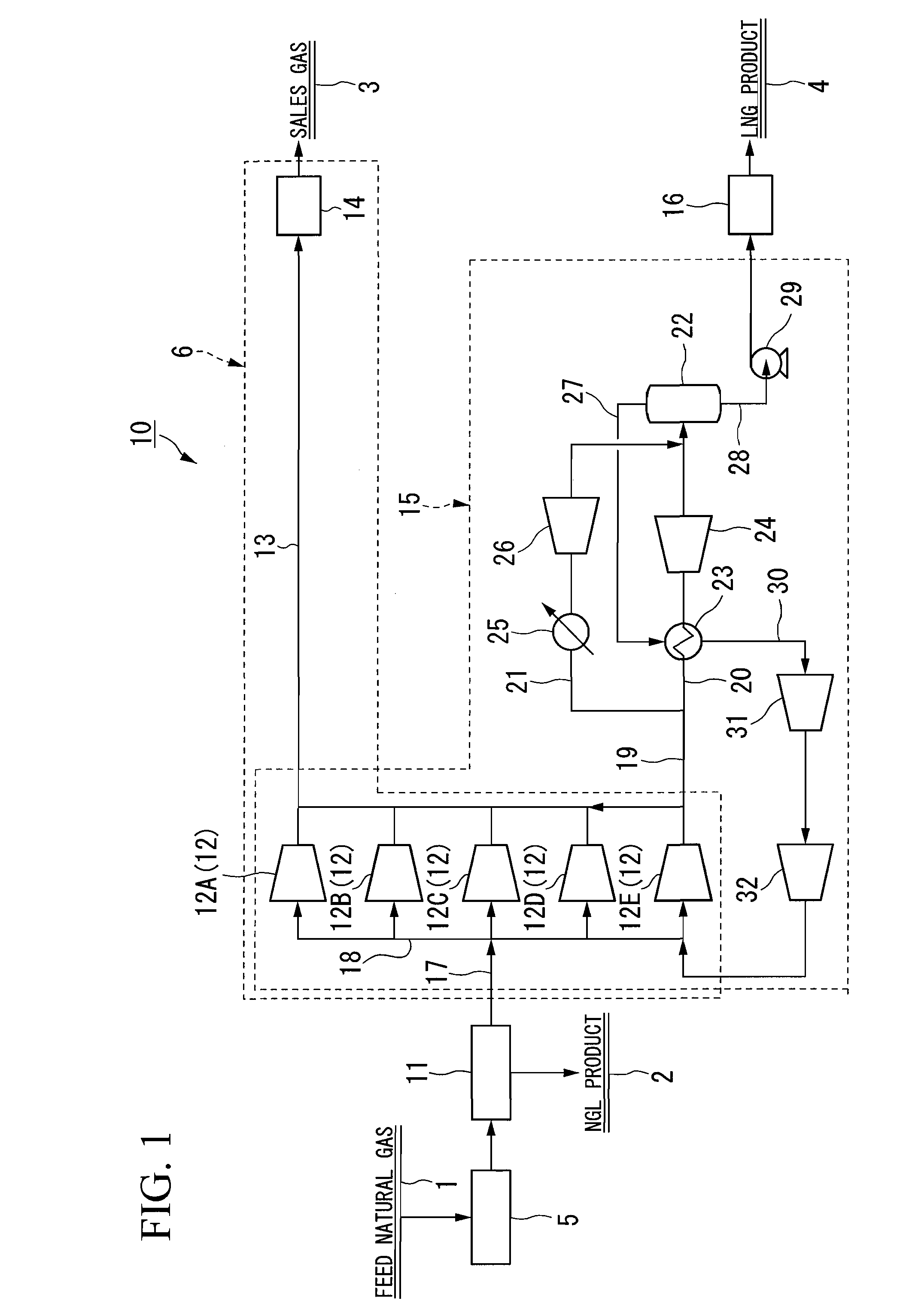
[0038]FIG. 1 is a schematic diagram illustrating a configuration of a natural gas processing plant for performing a natural gas processing method according to a first embodiment of the invention.

[0039]In FIG. 1, Reference Numeral 1 denotes a feed natural gas. Reference Numeral 2 denotes a natural gas liquid (NGL). Reference Numeral 3 denotes a sales gas. Reference Numeral 4 denotes liquefied natural gas (LNG). Reference Numeral 5 denotes a pretreatment plant. Reference Numeral 6 denotes a sales gas production plant. Reference Numeral 10 denotes an entire natural gas processing plant. Reference Numeral 11 denotes an NGL recovery plant. Reference Numeral 12 denotes sales gas compressors. Reference Numeral 13 denotes a line. Reference Numeral 14 denotes a sales gas pipeline. Reference Numeral 15 denotes a natural gas liquefying plant. Reference Numeral 16 denotes an LNG storing tank. Reference Numerals 17, 18, 19, 20, and 21 denote lines. Reference Numeral 22 denote...

second embodiment

(2) SECOND EMBODIMENT

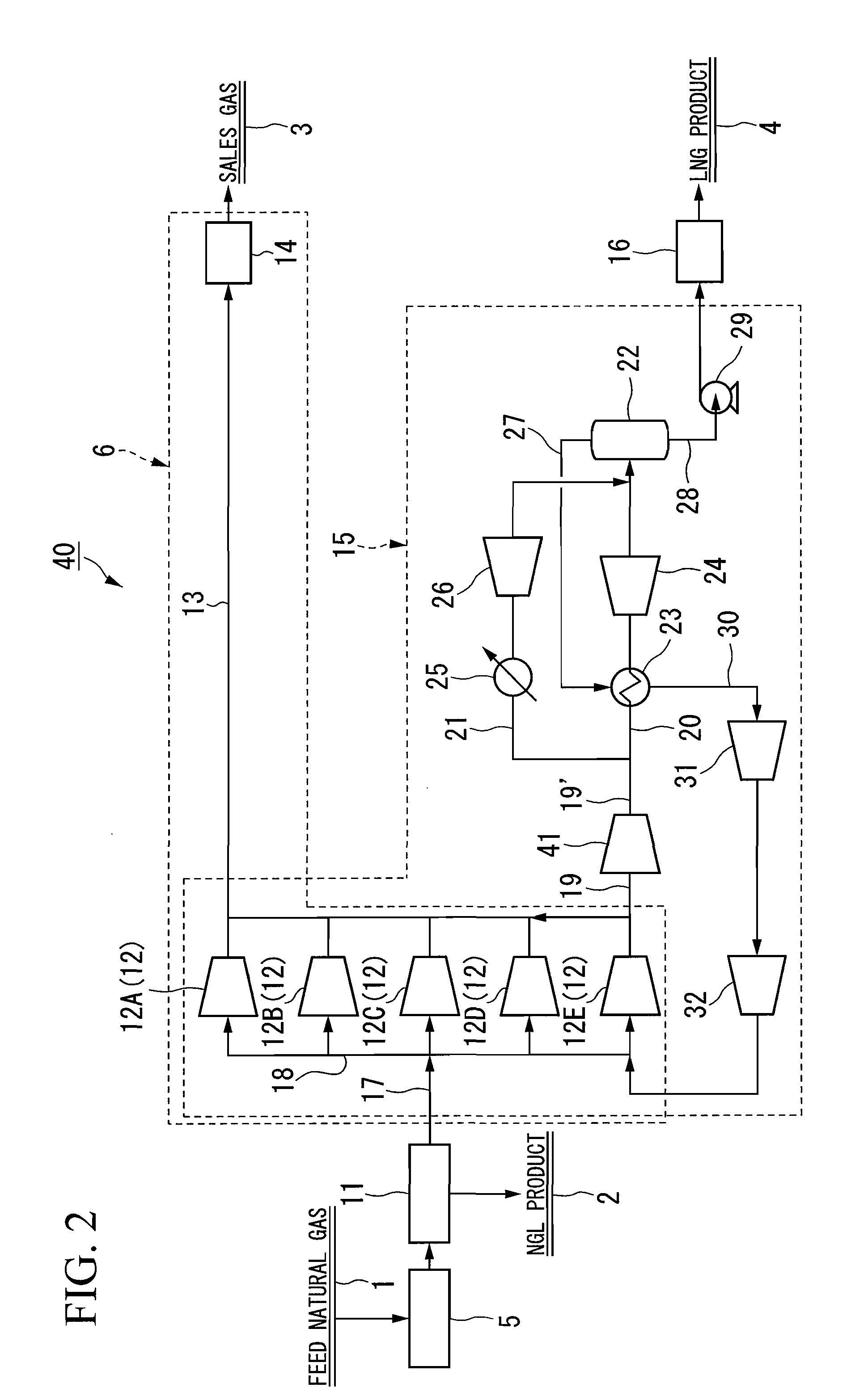
[0078]FIG. 2 is a schematic diagram illustrating a configuration of a natural gas processing plant for performing a natural gas processing method according to a second embodiment of the invention.

[0079]In FIG. 2, the same reference numerals are used for the same components as those of the natural gas processing plant 10 shown in FIG. 1 and explanations thereof are omitted.

[0080]A natural gas processing plant 40 is different from the above-described natural gas processing plant 10 in that a second gas compressor 41 compressing only an LNG feed gas is provided between a line 19 and a line 19′ and before a diverging point of lines 20 and 21. Other configurations are the same as those according to the above-described first embodiment.

[0081]Hereinafter, an operation of the natural gas processing plant 40 will be described and a method of processing a natural gas according to the second embodiment will be described.

[0082]First, a feed natural gas 1 obtained from a wel...

third embodiment

(3) THIRD EMBODIMENT

[0090]FIG. 3 is a schematic diagram illustrating a configuration of a natural gas processing plant 50 for performing a natural gas processing method according to a third embodiment of the invention.

[0091]In FIG. 3, the same reference numerals are used for the same components as those of the natural gas processing plant 10 shown in FIG. 1 and the explanations thereof are omitted.

[0092]A natural gas processing plant 50 according to the third embodiment is different from the above-described natural gas processing plant 10 in that the line 21 diverging from the line 20 in the midway of a line 19 in a natural gas liquefying plant 55 has different connected portions. Specifically, the line 21 is further diverged to provide a line for liquefying the LNG feed gas to obtain a product, and a line for transferring the LNG feed gas as a cooling medium. Other configurations are basically the same as those according to the above-described first embodiment.

[0093]In FIG. 3, Refe...


PUM


Abstract

A natural gas processing method includes: a pretreatment process of obtaining a treated natural gas; an NGL recovery process of cooling the treated natural gas obtained in the pretreatment process to recover an NGL product composed of ethane and heavier hydrocarbons and to separate a lean gas; a sales gas production process of compressing a part of the lean gas separated in the NGL recovery process to obtain a high-pressure gas; and a natural gas liquefying process of cooling the high-pressure gas after the high-pressure gas is obtained by compressing the lean gas separated in the NGL recovery process, to thereby obtain the LNG product. In the natural gas processing method, a gas compressor used in the sales gas production process is used as a gas compressor in the natural gas liquefying process.

Description

BACKGROUND OF THE INVENTION[0001]1. Field of the Invention[0002]Priority is claimed on Japanese Patent Application No. 2007-001187, filed Jan. 9, 2007, the content of which is incorporated herein by reference.[0003]The present invention relates to a natural gas processing method of recovering a natural gas liquid and a high-pressure sales gas from a natural gas as major products and recovering a liquefied natural gas as a co-product.[0004]2. Description of Related Art[0005]In general, a natural gas liquid (hereinafter, frequently referred to as “NGL”), a liquefied natural gas (hereinafter, frequently referred to as “LNG”), and a high-pressure sales gas (hereinafter, frequently referred to as “a sales gas”) are separated and recovered from a natural gas in consideration of market demand.[0006]Commercially available products from the natural gas excluding a self-fuel consumed in a plant are the above-mentioned three products including NGL, LNG, and the sales gas. However, there is no ...

Claims


Application Information

Patent Timeline
IPC IPC(8): F25J3/00
CPCF25J1/0208F25J2230/30F25J2220/64F25J2230/60F25J1/0022F25J1/0035F25J1/0037F25J1/004F25J1/0042F25J1/0052F25J1/0087F25J1/0229F25J1/025F25J1/0264F25J2220/62F25J2230/24F25J2210/06F25J2270/06F25J1/0082F25J1/005F25J1/021F25J1/0254F25J2270/60F25J3/0209F25J2215/62F25J3/0233F25J3/0242F25J2230/32F25J1/0237F25J3/0238F25J2260/20F25J2290/80F25J2270/12F25J1/0274
Inventor KONISHI, HITOSHIOMORI, HIDEFUMI
Owner JGC CORP
Why Eureka
Try Eureka