
Water removal and heavy-hydrocarbon removal process in liquefied natural gas production from mixed gas rich in methane

Active Publication Date: 2014-11-27
XINDI ENERGY ENG TECH
View PDF9 Cites 12 Cited by
  • Summary
  • Abstract
  • Description
  • Claims
  • Application Information

AI Technical Summary

Benefits of technology

This patent describes a system for removing moisture and heavy hydrocarbons from gas using a composite bed. The system has a reduced investment and energy consumption. The process uses an isobaric drying and heavy hydrocarbon removal method, which increases the lifespan of the valve. The system does not require a purified gas as the regenerating gas, simplifying the flow scheme and making the system more convenient to start or stop. The use of a three-tower flow scheme with cold blowing operation lowers energy consumption.

Problems solved by technology

The traditional mode of transportation and supply by pipeline still remains a mainstream, but due to the limitation from gas-feed conditions and consumer distribution, a large part of energy resources cannot be transported by pipeline in long distance, so we have to select a liquefying mode, i.e., we transform the methane gas to a liquid and then use a flexible mode of transportation to transport the liquid to user terminals.
As to the operating conditions of several LNG apparatuses put into service in China, the front-end purifying section of gas mixture usually utilizes an acidic gas removing unit, a drying and adsorbing unit, and a heavy hydrocarbon removing unit, etc. to remove impurity components in successive steps, the drawbacks of these operating conditions consist in that the equipment investment is higher and the energy consumption of the system under normal operating mode is also higher.

Method used


Image

  • Water removal and heavy-hydrocarbon removal process in liquefied natural gas production from mixed gas rich in methane
  • Water removal and heavy-hydrocarbon removal process in liquefied natural gas production from mixed gas rich in methane

Examples


Embodiment Construction

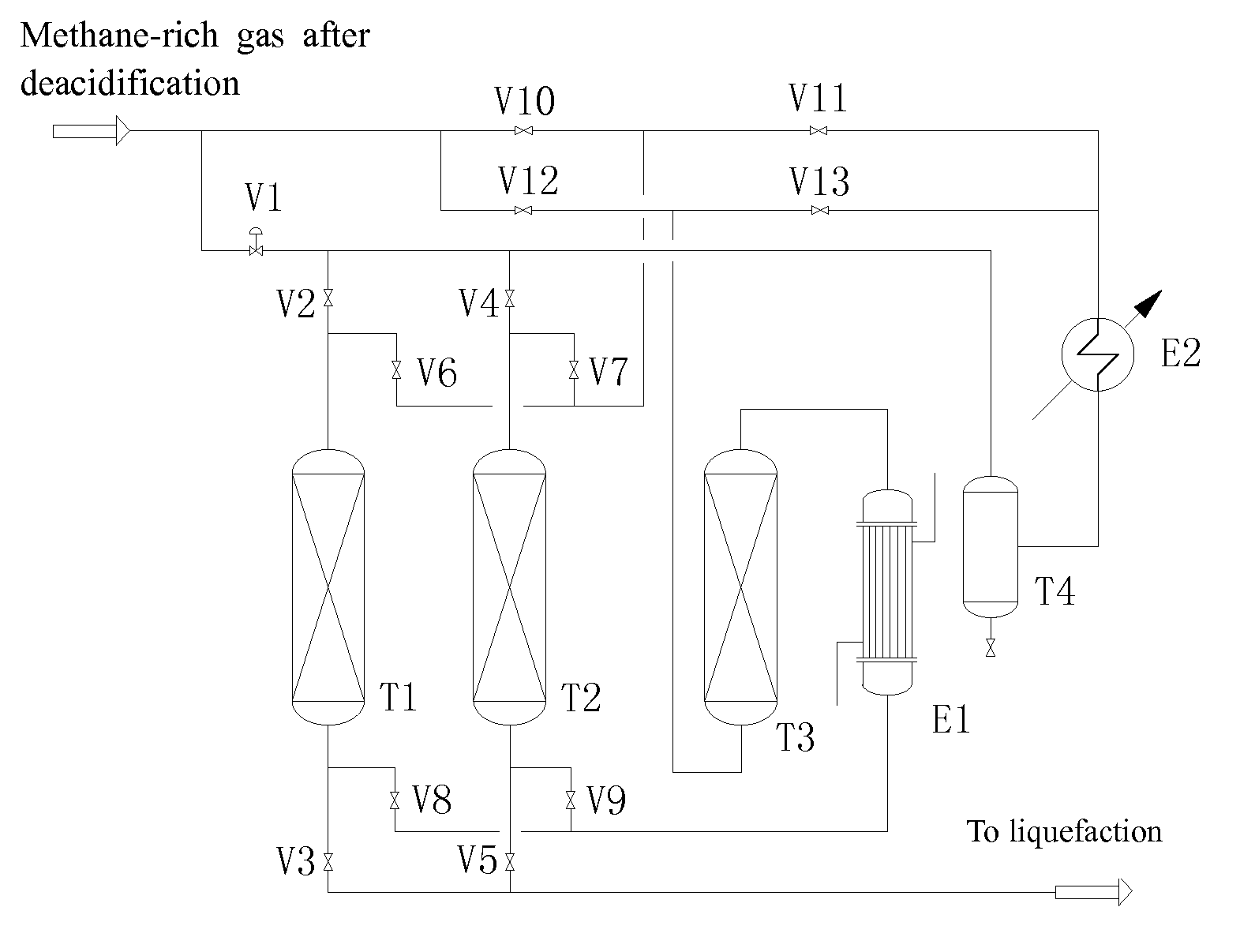
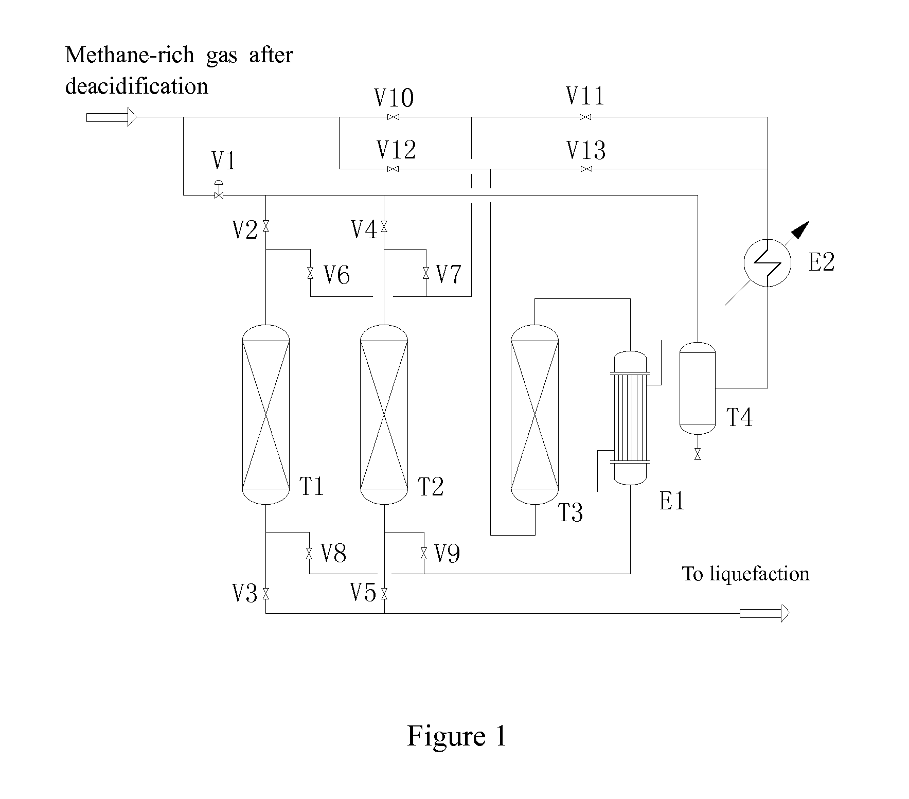
[0034]The present invention provides a process for drying / dehydrating and heavy hydrocarbon removing in combination in the production of liquefied natural gas from a methane-rich gas mixture, wherein the process utilizes the composite adsorbent bed(s) to remove the moisture and the heavy hydrocarbons simultaneously; the methane-rich gas mixture after deacidification treatment is subjected continually to the three-tower isobaric drying treatment, and these treatments utilize composite adsorbent bed(s) to remove simultaneously the moisture and heavy hydrocarbons from the gas mixture stream, wherein the moisture is removed such that the dew point at normal pressure (or atmosphere pressure) is ≦−76° C. and the heavy hydrocarbon components of C6 and higher (i.e., >C6) are removed such that the content of these components is ≦217 ppm (preferably ≦200 ppm, more preferably ≦100 ppm, further preferably ≦50 ppm, and most preferably ≦10 ppm). Further, a part of methane-rich gas mixture as a re...


PUM


Abstract

A process for dehydrating and removing heavy hydrocarbons in the production of liquefied natural gas from a methane-rich gas mixture is disclosed, wherein the methane-rich gas mixture subjected to deacidification treatment is divided into two streams, i.e. the first stream and the second stream, wherein the first stream used as a system process gas is introduced into a drying procedure, and the second stream used as regenerating gas is introduced into a regenerating procedure; the first stream is subjected to a drying treatment, and the moisture and the heavy hydrocarbons are simultaneously removed from the first stream in a composite adsorbent bed(s) of a drying tower, wherein the moisture is removed such that the dew point at normal pressure is ≦−76° C. and the heavy hydrocarbon components of C6 and higher are removed such that the content of these components is ≦217 ppm; and the second stream is used as a regenerating gas in the regenerating procedure of the above-mentioned drying tower, subjected to a regenerating process, and then returned as a part of the system process gas. Comparing to those conventional processes, the present invention can achieve good purifying effect, lower equipment investment and late-stage energy consumption of the system, increase utilization ratio of feed gas, and the operation target of each unit becomes more clear and easy to control. The present invention further relates to an apparatus for carrying out the process.

Description

FIELD OF THE INVENTION [0001]The present invention relates to a front-end purifying treatment technology in the methane-rich gas cryogenic liquefaction, more specifically a process for dehydrating and removing heavy hydrocarbons in production of liquefied natural gas (LNG) from a methane-rich gas mixture and an apparatus for this process.BACKGROUND OF THE INVENTION [0002]Due to the pressure from environment protection and energy source cost, the using proportion of the natural gas, as a kind of primary energy, in various fields of the society is gradually promoted, and the market requirement for natural gas is also rapidly increased. The traditional mode of transportation and supply by pipeline still remains a mainstream, but due to the limitation from gas-feed conditions and consumer distribution, a large part of energy resources cannot be transported by pipeline in long distance, so we have to select a liquefying mode, i.e., we transform the methane gas to a liquid and then use a ...

Claims


Application Information

Patent Timeline
IPC IPC(8): F25J3/06
CPCF25J3/061F25J3/0635B01D53/0423B01D53/0462B01D2256/245B01D2257/702B01D2259/40001B01D2259/402B01D2259/416C10L2290/12C10L2290/543C10L3/101C10L3/106C10L2290/08C10L2290/541Y02C20/20B01D2257/80C10L3/102C10L2290/542B01D2259/406
Inventor XUAN, YONGGENXU, HUAZHOU
Owner XINDI ENERGY ENG TECH
Learn More