Liquid natural gas processing

a natural gas and processing technology, applied in the direction of liquidification, lighting and heating equipment, refrigeration and liquidation, etc., to achieve the effect of reducing the overall energy and fuel requirements, avoiding the need for dehydration, and reducing the capital investmen

Inactive Publication Date: 2006-11-23
HOWE BAKER ENGINEERS LTD
View PDF22 Cites 11 Cited by
  • Summary
  • Abstract
  • Description
  • Claims
  • Application Information

AI Technical Summary

Benefits of technology

[0006] As stated, our invention is directed to an improved process for the recovery of NGL from LNG which avoids the need for dehydration, the removal of acid gases and other impurities. A further advantage of our process is that it significantly reduces the overall energy and fuel requirements because the residue gas compression requirements associated with a typical NGL recovery facility are virtually eliminated. Our process also does not require a large pressure drop across a turbo-expander or J.T. value to generate cryogenic temperatures. This reduces the capital investment to construct our process by 30 to 50% compared to a typical cryogenic NGL recovery facility.
[0007] In general, our process recovers hydrocarbons heavier than methane using low pressure liquefied natural gas (for example, directly from an LNG storage system) by using a two step separation process where the C2+ hydrocarbons recovered in the first separation (recovery) stage are split and a portion is heated before entering the second separation stage and the other portion is used as a reflux stream in the second separation step. This aids in the recovery of the heavier than methane hydrocarbons, thus producing high yields of NGL. The C1-C2 rich stream recovered overhead in the second separation step is recycled to the first separation step to produce a methane-rich stream. This methane-rich stream from the first separation step is routed to the suction side of a low temperature, low head compressor to re-liquefy the methane-rich stream. This re-liquefied LNG is then split, with a portion being used as the second reflux in the first separation stage and the remaining portion directed to main LNG export pumps.

Problems solved by technology

Although there are many known processes, there is always a compromise between high recovery and process simplicity (i.e., low capital investment).

Method used


Image

  • Liquid natural gas processing
  • Liquid natural gas processing

Examples


Embodiment Construction

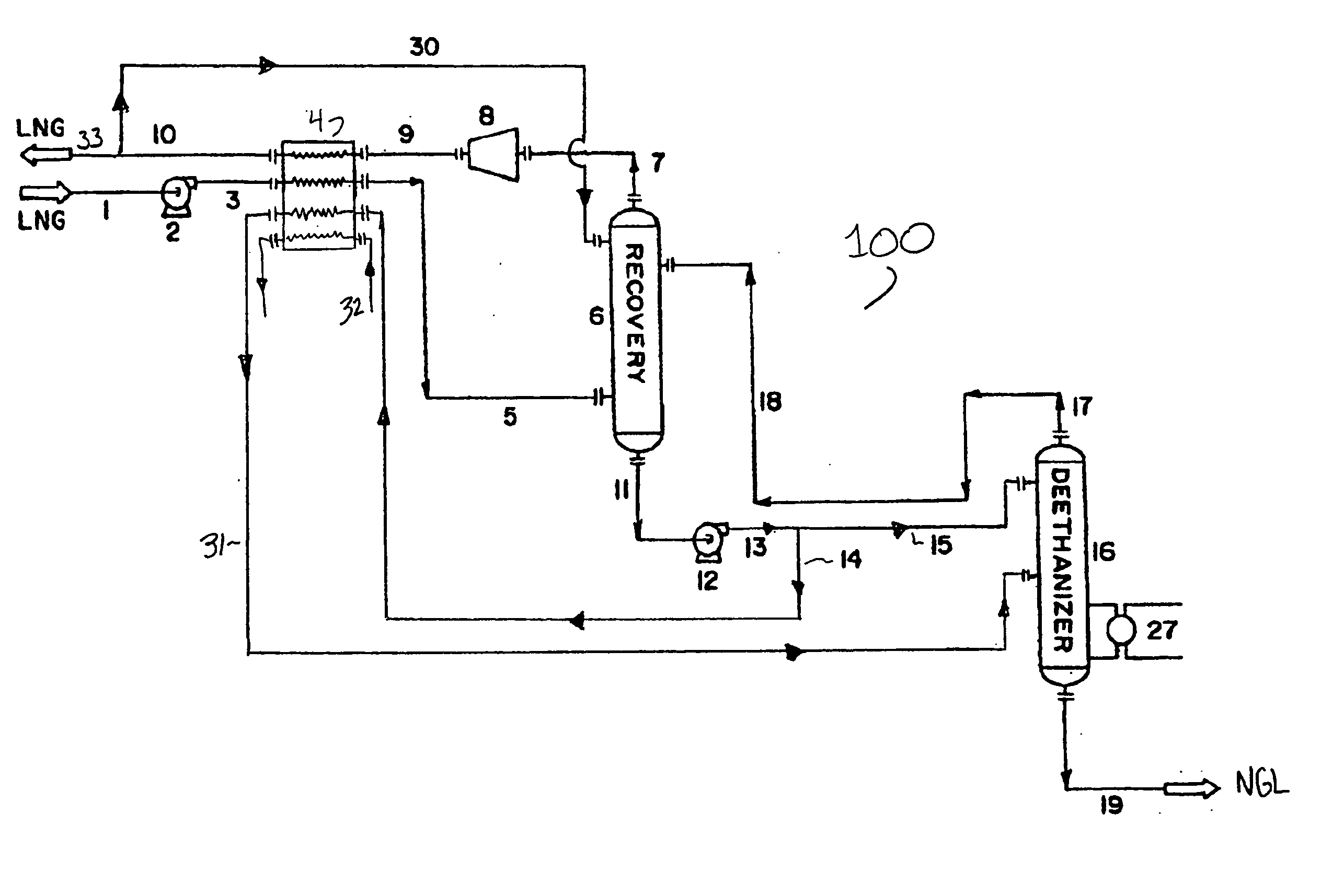
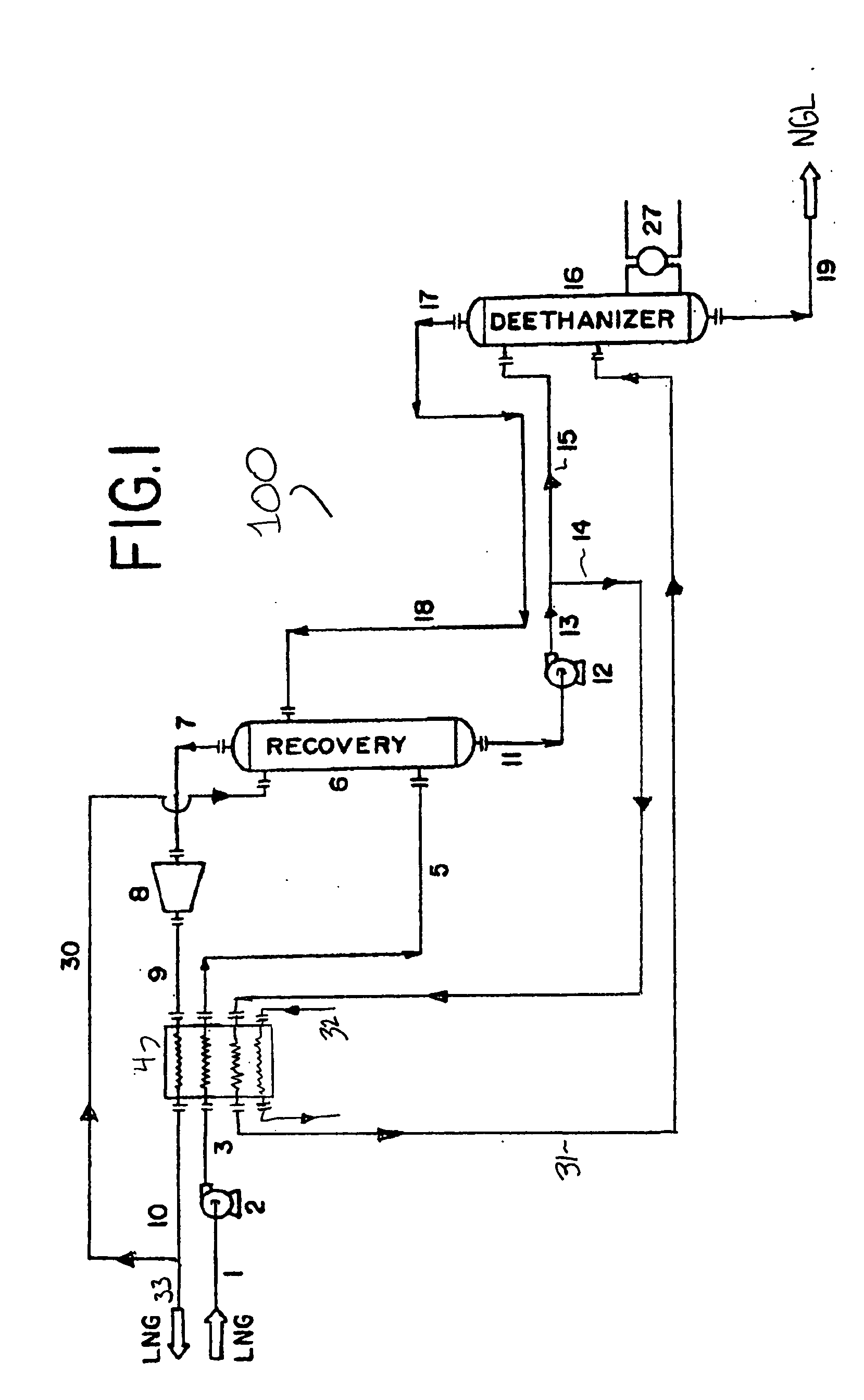
[0009] Natural gas liquids (NGL) are recovered from low-pressure liquefied natural gas (LNG) without the need for external refrigeration or feed turboexpanders as used in prior processes. Referring to FIG. 1, process 100 shows the incoming LNG feed stream 1 enters pump 2 at very low pressures, typically in the range of 0-5 psig and at a temperature of less than −200° F. Pump 2 may be any pump design typically used for pumping LNG provided that it is capable of increasing the pressure of the LNG several hundred pounds to approximately 100-500 psig, preferably the process range of 300-350 psig. The resultant stream 3 from pump 2 is physically fed to cold box 4 where it is cross-exchanged with substantially NGL-free residue gas in line 9 obtained from the discharge of compressor 8. In those circumstances where additional cooling is necessary in cold box 4, an external refrigerant line 32 may be employed to increase the cooling capacity. Although the exact nature of the external refrige...


PUM


Abstract

A process for the recovery of natural gas liquids (NGL) from liquefied natural gas (LNG) is disclosed. The LNG feed stream is subjected to a two stage separation process where the bottoms from the first stage separation containing C2+ hydrocarbons is split into two portions, with one portion being heated and used as a reflux during the second stage separation to recover the NGL product.

Description

RELATED APPLICATIONS [0001] This application is a continuation-in-part application of co-pending application U.S. Ser. No. 10 / 115,150, filed Apr. 3, 2002.FIELD OF THE INVENTION [0002] The present invention is directed toward the recovery of hydrocarbons heavier than methane from liquefied natural gas (LNG) and in particular to a two step separation process where the C2+ hydrocarbons recovered in the first separation stage are split and a portion is heated before entering the second separation stage to aid in the recovery of the heavier than methane hydrocarbons. BACKGROUND OF THE INVENTION [0003] Natural gas typically contains up to 15 vol. % of hydrocarbons heavier than methane. Thus, natural gas is typically separated to provide a pipeline quality gaseous fraction and a less volatile liquid hydrocarbon fraction. These valuable natural gas liquids (NGL) are comprised of ethane, propane, butane, and minor amounts of other heavy hydrocarbons. In some circumstances, as an alternative ...

Claims


Application Information

Patent Timeline
Patent Type & Authority Applications(United States)
IPC IPC(8): F25J3/00F25J3/02F25J3/06
CPCF25J3/0214F25J2245/90F25J3/0238F25J3/0242F25J3/0615F25J3/0635F25J3/064F25J2200/02F25J2200/04F25J2205/02F25J2210/06F25J2215/62F25J2230/08F25J2230/60F25J2235/60F25J2245/02F25J3/0233F25J3/00F25J3/02
Inventor SCHROEDER, SCOTTREDDICK, KENNETHBELHATECHE, NOUREDDINE
Owner HOWE BAKER ENGINEERS LTD
Why Eureka
Try Eureka