System and method to measure hydrocarbons produced from a well

a well and hydrocarbon technology, applied in the direction of positive displacement liquid engine, wellbore/well accessories, separation processes, etc., can solve the problems of unfavorable environmental protection, unfavorable environmental protection, and high cost of operating vru, so as to reduce environmental emissions and accurate determination of royalties , the effect of accurate metering

Inactive Publication Date: 2016-05-12
CROSSSTREAM ENERGY
View PDF1 Cites 21 Cited by
  • Summary
  • Abstract
  • Description
  • Claims
  • Application Information

AI Technical Summary

Benefits of technology

[0018]The present invention provides a method and a system for producing oil that satisfies some or all of the aforementioned needs. The present invention provides a method of and a system for maintaining the position of a liquid / gas interface within a separator within a given range. The present invention provides a method of accurately metering oil at a well as it is removed from a separator and without de-pressuring the oil for storage in a stock tank. The present invention comprises a method of economically reducing environmental emissions associated with oil production while providing for the accurate determination of royalties due the lease owner. The present invention provides a method of simultaneously reducing capital investment in field production facilities needed for producing multiple wells while eliminating sources of unwanted environmental emissions. The present invention provides a method of and a system for obtaining greater utility from production facilities operated at the lease, lower investment in production facilities and a greater return on investment in production facilities used to produce the lease. These advantages are obtained by providing a production facility system that enables an operator to economically and reliably turndown (i.e., reduce capacity of) the production facility as the production capacity of the well declines. By providing only as much production facility capacity as is actually needed, the overall investment in a plurality of wells can be minimized and the return on investment in production facilities can be increased. This aspect of the invention is especially beneficial where oil-producing wells exhibit a steeply-declining production capacity with an inordinately large portion of the total recoverable hydrocarbons produced within months or even weeks of the onset of production. This type of production capacity decline is characteristic of wells that produce from fractured shale formations.

Problems solved by technology

A VRU for a stock tank is expensive to purchase, install and to operate because of the large compression ratio required to compress nearly-atmospheric gas off the stock tank to the pressure of the gas stream from the low-pressure separator.
Generally, the cost of operating a VRU will exceed any economic benefit of capturing the hydrocarbons that evaporate in the stock tank.
As a result, many operators forego the capture of stock tank vapors and instead incinerate stock tank vapors, thereby resulting in unwanted environmental emissions.
Disadvantages of the use of conventional production facilities and a stock tank include economic loss and environmental pollution.
In addition, motors needed to drive compressors require large amounts of energy and, depending on the energy source, may result in the release of additional unwanted combustion products into the environment.
When a compressor or a VRU fails, the lighter hydrocarbon components that inevitably evaporate from produced oil must be incinerated to sustain production, thereby resulting in further unwanted emissions.
Another costly consequence of using conventional production facilities for producing a well relates to excessive volatility deductions for oil delivered to a purchaser from a stock tank.
In addition to unwanted deductions in the price obtainable for oil sold to a purchaser, some pipeline operators impose strict limits on the vapor pressure of oil to be shipped through pipelines to prevent entrained light hydrocarbon components from evaporating and creating a gas phase that impairs pipeline capacity and operations.

Method used


Image

  • System and method to measure hydrocarbons produced from a well
  • System and method to measure hydrocarbons produced from a well
  • System and method to measure hydrocarbons produced from a well

Examples


Embodiment Construction

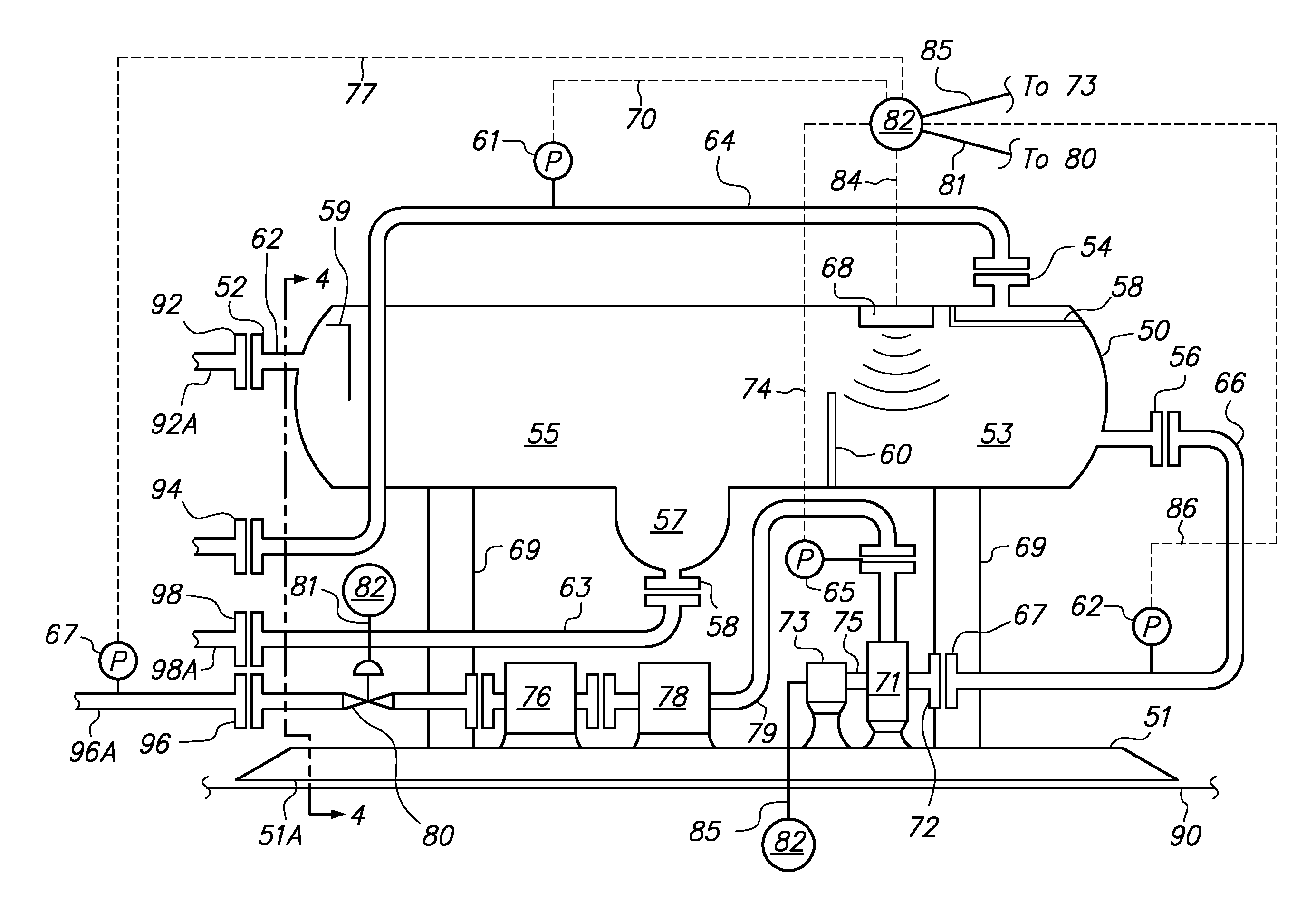
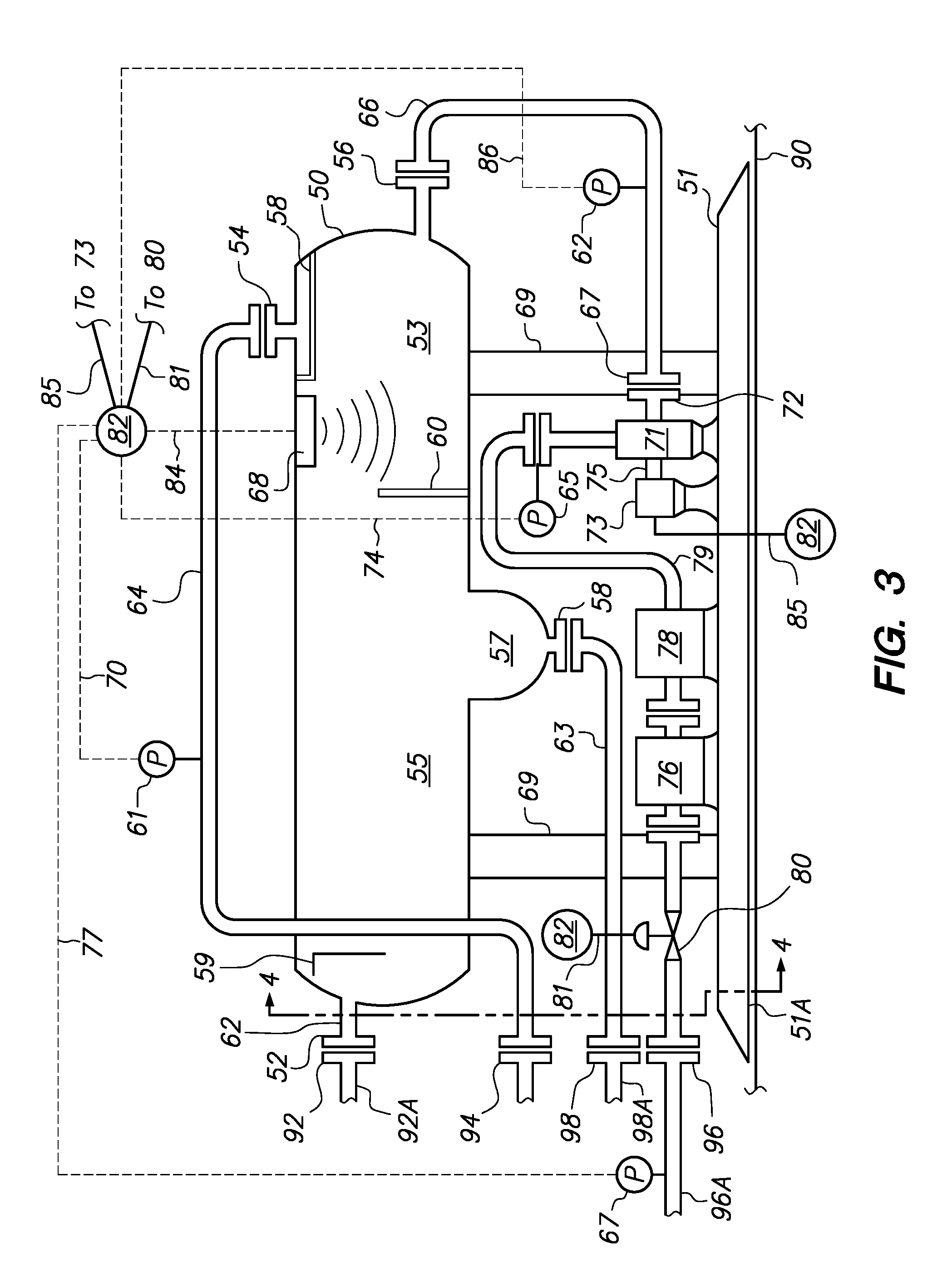
[0032]The present invention provides a method of economically and environmentally optimizing production facilities for producing wells drilled in oil-bearing geologic formations. In one embodiment, the present invention provides an improved method of controlling the liquid (or oil) level in a separator used to process production from a well while accurately measuring, at a high pressure, liquid (or oil) produced by the well.

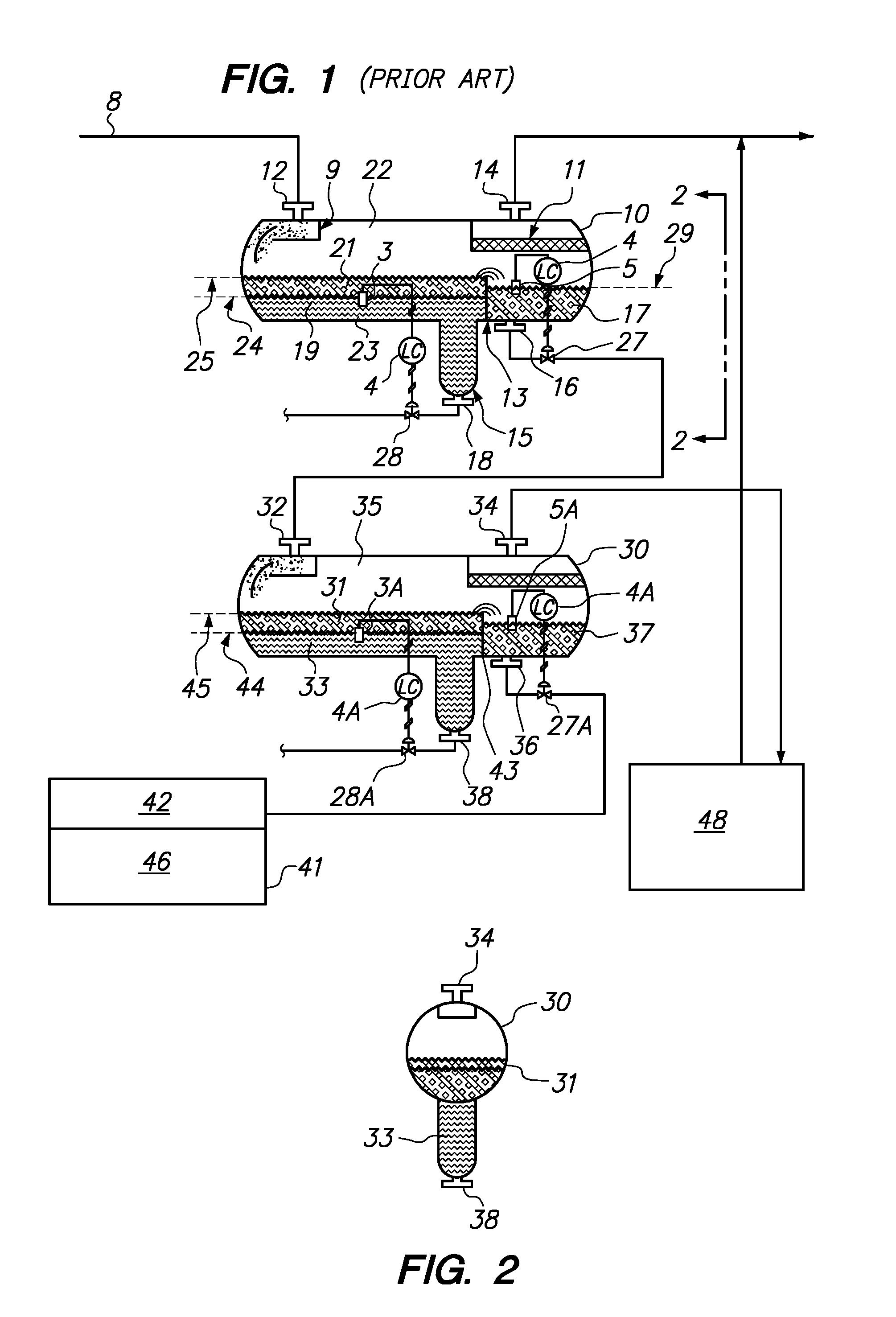
[0033]The disclosure that follows uses the term “liquid” in referring to a fluidic material produced from a geologic formation and separated from a gas phase in a separator. The term “liquid,” as used herein, may refer to oil or, in the alternative, the term “liquid” may refer to a mixture of water and oil that, for example, might be obtained from a two-phase separator.

[0034]The measurement of liquid production at high pressure prevents the need for a large number of vessels and related processing equipment to produce the well, and prevents the need for a much la...


PUM


Abstract

A method and system for metering liquid production at a well comprises an actuated back pressure control valve, a liquid pump, a liquid flow meter and a pressure sensor, both intermediate the liquid pump and the back pressure control valve, and a separator having a liquid discharge conduit, a pressure sensor and a liquid / gas interface sensor disposed to monitor a section of the separator. The liquid pump receives a stream of liquid removed from the monitored section of the separator and moves the liquid stream through the flow meter and the back pressure control valve. A controller receives signals from the pressure sensors and the interface sensor, and operates the liquid pump at a speed to maintain an interface in the monitored section within a predetermined range while positioning the back pressure control valve to maintain the pressure at the flow meter above a pressure at which bubbles may form.

Description

STATEMENT OF RELATED APPLICATION[0001]This divisional application depends from and claims priority to U.S. Non-Provisional application Ser. No. 13 / 458,987 filed on Apr. 27, 2012, which depends from and claims priority to U.S. Provisional Application No. 61 / 485,479 filed on May 12, 2011.BACKGROUND[0002]1. Field of the Invention[0003]This invention relates to a system and a method to measure liquid, such as oil, produced from an earthen well drilled into the Earth's crust.[0004]2. Background of the Invention[0005]Earthen wells are drilled into the Earth's crust to access mineral deposits such as oil and gas. Technological advances in drilling technology have enabled sections of a well to be drilled horizontally, or at a highly-deviated angle from vertical, and within a targeted geologic formation to dramatically increase the surface area through which fluids residing in the geologic formation (hydrocarbons) may feed into the completed section of the well. Where wells are drilled in ge...

Claims


Application Information

Patent Timeline
Patent Type & Authority Applications(United States)
IPC IPC(8): B01D17/12B01D17/04E21B43/34
CPCB01D17/12E21B43/34B01D17/047B01D17/0214B01D19/0063E21B49/00E21B49/087F04B13/00E21B49/0875
Inventor BLACK, RICHARD
Owner CROSSSTREAM ENERGY
Why Eureka
Try Eureka