Simulating the Dynamic Response of a Drilling Tool Assembly and Its Application to Drilling Tool Assembly Design Optimization and Drilling Performance Optimization

a drilling tool and dynamic response technology, applied in the field of drilling wellbore, can solve the problems of large fluctuation in the wob, torsional, axial and lateral vibration of drilling tool assemblies, and damping is typically not enough to suppress vibrations completely, so as to optimize the drilling performance of drilling tool assemblies

Inactive Publication Date: 2007-03-22
SMITH INT INC
View PDF27 Cites 133 Cited by
  • Summary
  • Abstract
  • Description
  • Claims
  • Application Information

AI Technical Summary

Problems solved by technology

However, in most cases, the majority of the fluctuation in the WOB can be attributed to drilling tool assembly vibrations.
In general, drilling tool assemblies may experience torsional, axial and lateral vibrations.
Although partial damping of vibration may result due to viscosity of drilling fluid, friction of the drill pipe rubbing against the wall of the wellbore, energy absorbed in drilling the formation, and drilling tool assembly impacting with wellbore wall, these sources of damping are typically not enough to suppress vibrations completely.
Up to now, vibrations of a drilling tool assembly have been difficult to predict because different forces may combine to produce the various modes of vibration, and models for simulating the response of an entire drilling tool assembly including roller cone bit interacting with formation in a drilling environment have not been available.
However, drilling tool assembly vibrations are generally undesirable, not only because they are difficult to predict, but also because they can significantly affect the instantaneous force applied on the bit.
This can result in the bit not operating as expected.
For example, vibrations can result in off-centered drilling, slower rates of penetration, excessive wear of the cutting elements, or premature failure of the cutting elements and the bit.
Lateral vibration of the drilling tool assembly may be a result of radial force imbalances, mass imbalance, and bit / formation interaction, among other things.
Lateral vibration results in poor drilling tool assembly performance, overgage hole drilling, out-of-round, or “lobed” wellbores and premature failure of both the cutting elements and bit bearings.
Because the length of a drilling tool assembly may extend for more than a mile, pipe trips can take several hours and can pose a significant expense to the wellbore operator and drilling budget.
However, no prior art simulation techniques have been developed to cover the dynamic modeling of an entire drilling tool assembly.
As a result, the dynamic response of a drilling tool assembly or the effect of a change in configuration on drilling tool assembly performance can not be accurately predicted.
While prior art simulation methods, such as those described above cover either the interaction of the bit with the formation or the BHA dynamics, no prior art simulation technique has been developed to cover the dynamic modeling of the entire drilling tool assembly.
As a result, accurately predicting the response of a drilling tool assembly has been virtually impossible.
Additionally, the change in the dynamic response of a drilling tool assembly when a component of the drilling tool assembly is changed is not well understood.

Method used


Image

  • Simulating the Dynamic Response of a Drilling Tool Assembly and Its Application to Drilling Tool Assembly Design Optimization and Drilling Performance Optimization
  • Simulating the Dynamic Response of a Drilling Tool Assembly and Its Application to Drilling Tool Assembly Design Optimization and Drilling Performance Optimization
  • Simulating the Dynamic Response of a Drilling Tool Assembly and Its Application to Drilling Tool Assembly Design Optimization and Drilling Performance Optimization

Examples


Embodiment Construction

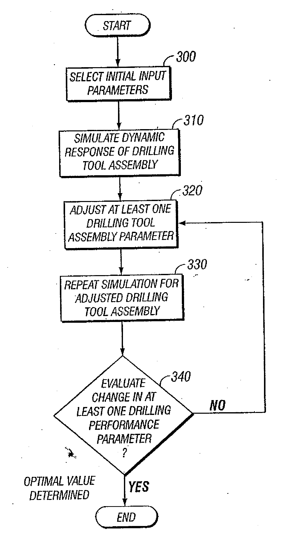
[0038] The invention provides methods for simulating the dynamic response of a drilling tool assembly drilling an earth formation, methods for optimizing a drilling tool assembly design, and methods for optimizing drilling tool assembly performance.

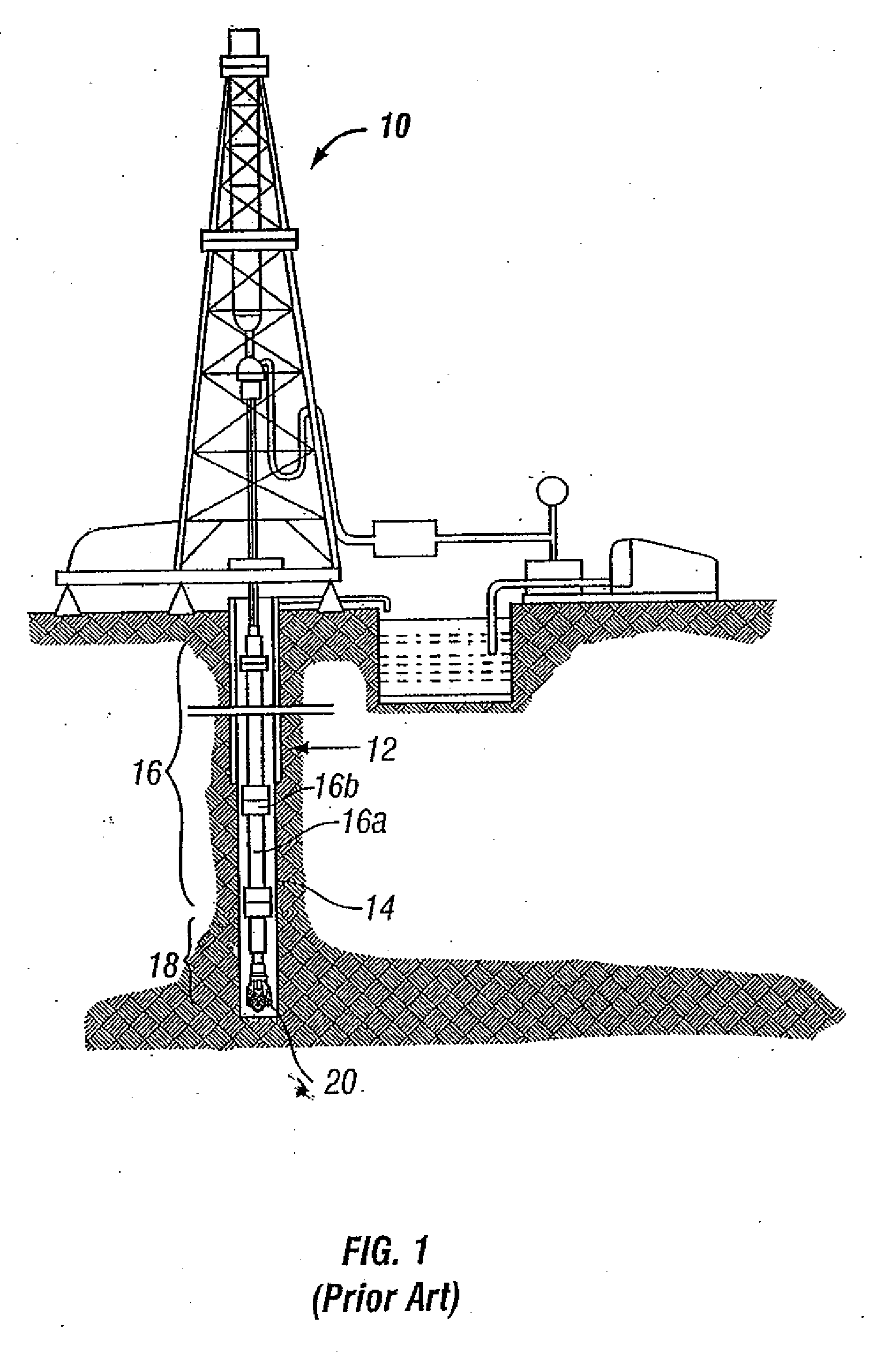
[0039] In accordance with the invention, a drilling tool assembly comprises at least one segment (or joint) of drill pipe and a drill bit. The components of a drilling tool assembly may be more generally referred to as a drill string and a bottomhole assembly (BHA). The drill string comprises one or more joints of drill pipe. The BHA comprises at least a drill bit.

[0040] In a typical drilling tool assembly, the drill string comprises several joints of drill pipe connected end to end, and the bottomhole assembly comprises one or more drill collars and a drill bit attached to an end of the BHA. The drill string may further include additional components, such as a kelly, kelly cocks, blowout preventers, safety valves, etc. The BHA may furt...


PUM


Abstract

A method of selecting a drilling tool assembly including selecting components of a first drilling tool assembly and simulating a dynamic response of the first drilling tool assembly. Further, selecting components of a second drilling tool assembly, simulating a dynamic response of the second drilling tool assembly, and graphically illustrating the dynamic responses of the first and second drilling tool assemblies.

Description

CROSS-REFERENCE TO RELATED APPLICATIONS [0001] This application claims priority from U.S. patent application Ser. No. 10 / 852,574 filed on May 24, 2004.FIELD OF THE INVENTION [0002] The invention relates generally to drilling a wellbore, and more specifically to simulating the drilling performance of a drilling tool assembly drilling a wellbore. In particular, the invention relates to methods for simulating the dynamic response of a drilling tool assembly, methods for optimizing a drilling tool assembly design, and methods for optimizing the drilling performance of a drilling tool assembly. BACKGROUND OF THE INVENTION [0003]FIG. 1 shows one example of a conventional drilling system for drilling an earth formation. The drilling system includes a drilling rig 10 used to turn a drilling tool assembly 12 which extends downward into a wellbore 14. The drilling tool assembly 12 includes a drilling string 16, and a bottomhole assembly (BHA) 18, attached to the distal end of the drill string...

Claims


Application Information

Patent Timeline
Patent Type & Authority Applications(United States)
IPC IPC(8): G06G7/48E21B10/00E21B44/00
CPCE21B44/00E21B10/00
Inventor HUANG, SUJIAN
Owner SMITH INT INC
Why Eureka
Try Eureka