Liquified natural gas (LNG) fueled combined cycle power plant and a (LNG) fueled gas turbine plant

a combined cycle power plant and natural gas technology, applied in the direction of machines/engines, efficient propulsion technologies, container discharge methods, etc., can solve the problems of small utilization of cold potential and waste of cold potential, and achieve the effect of improving the capacity of a combined cycle plan

Inactive Publication Date: 2002-04-23
SUEZ LNG NA
View PDF19 Cites 150 Cited by
  • Summary
  • Abstract
  • Description
  • Claims
  • Application Information

AI Technical Summary

Benefits of technology

At a few terminals, the cold potential is utilized in air separation plants or similar cryogenic installations or for refrigeration purposes in the freezing and storing of foodstuffs. It has also been proposed to use the cold LNG as a heat sink in a power cycle to generate electrical energy. A number of possible cycles have been proposed which seek to overcome the difficulties caused by the large temperature difference through which the LNG is heated and the particular shape of the warming curve. However, it has been found that even with relatively simple cycles only a small part of the available cold potential can be utilized. Proposals to increase the efficiency employ more complex cycles involving a large number of turbines operating between different pressure levels.
In our parent application, the invention broadly embodied a system and process which improved the capacity of a combined cycle plant in an amount up to 9% and the efficiency of the plant up to about 2%, particularly when the ambient temperature exceeded 60.degree. F. A LNG fuel supply system was used in combination with the combined cycle plant. A primary heat exchange fluid was chilled, in a two step process, in the LNG fuel supply system and was then utilized in the gas turbine process to cool and densify the intake air to the gas turbine. The primary heat exchange fluid was also utilized in the steam turbine process to condense the spent stream from the steam turbine. Lastly, the primary heat exchange fluid was recycled to the LNG fuel supply system where it was rechilled. The primary heat exchange fluid flowed through a closed loop while cooling and densifying the intake air, while condensing the steam discharged from the steam turbine and when being rechilled in the LNG fuel supply system.

Problems solved by technology

Although many suggestions have been made and some installations have been built to utilize the large cold potential of the LNG, in most receiving terminals the cold potential is wasted and the LNG is simply heated with a large flow of sea water which has to be applied in such a manner as to avoid ice formation.
However, it has been found that even with relatively simple cycles only a small part of the available cold potential can be utilized.

Method used


Image

  • Liquified natural gas (LNG) fueled combined cycle power plant and a (LNG) fueled gas turbine plant
  • Liquified natural gas (LNG) fueled combined cycle power plant and a (LNG) fueled gas turbine plant
  • Liquified natural gas (LNG) fueled combined cycle power plant and a (LNG) fueled gas turbine plant

Examples


Embodiment Construction

)

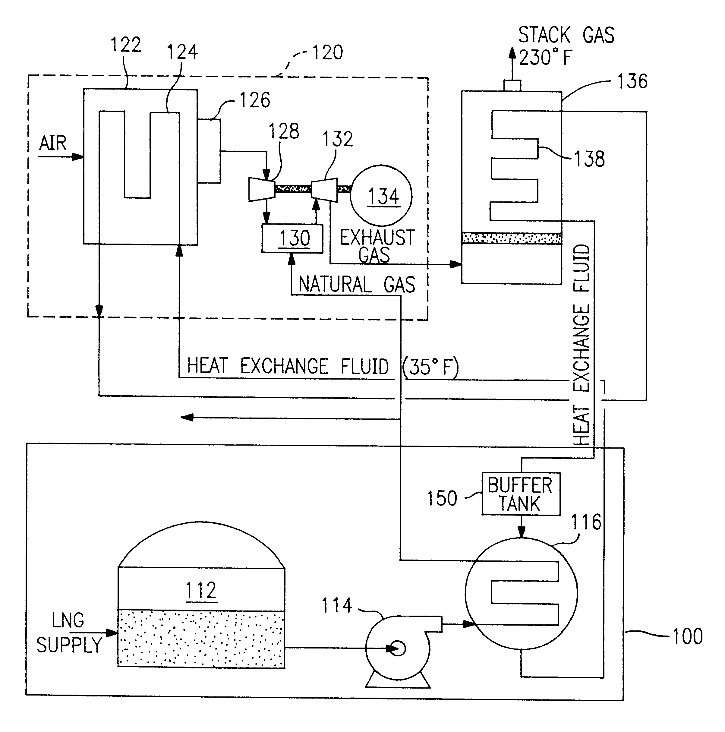
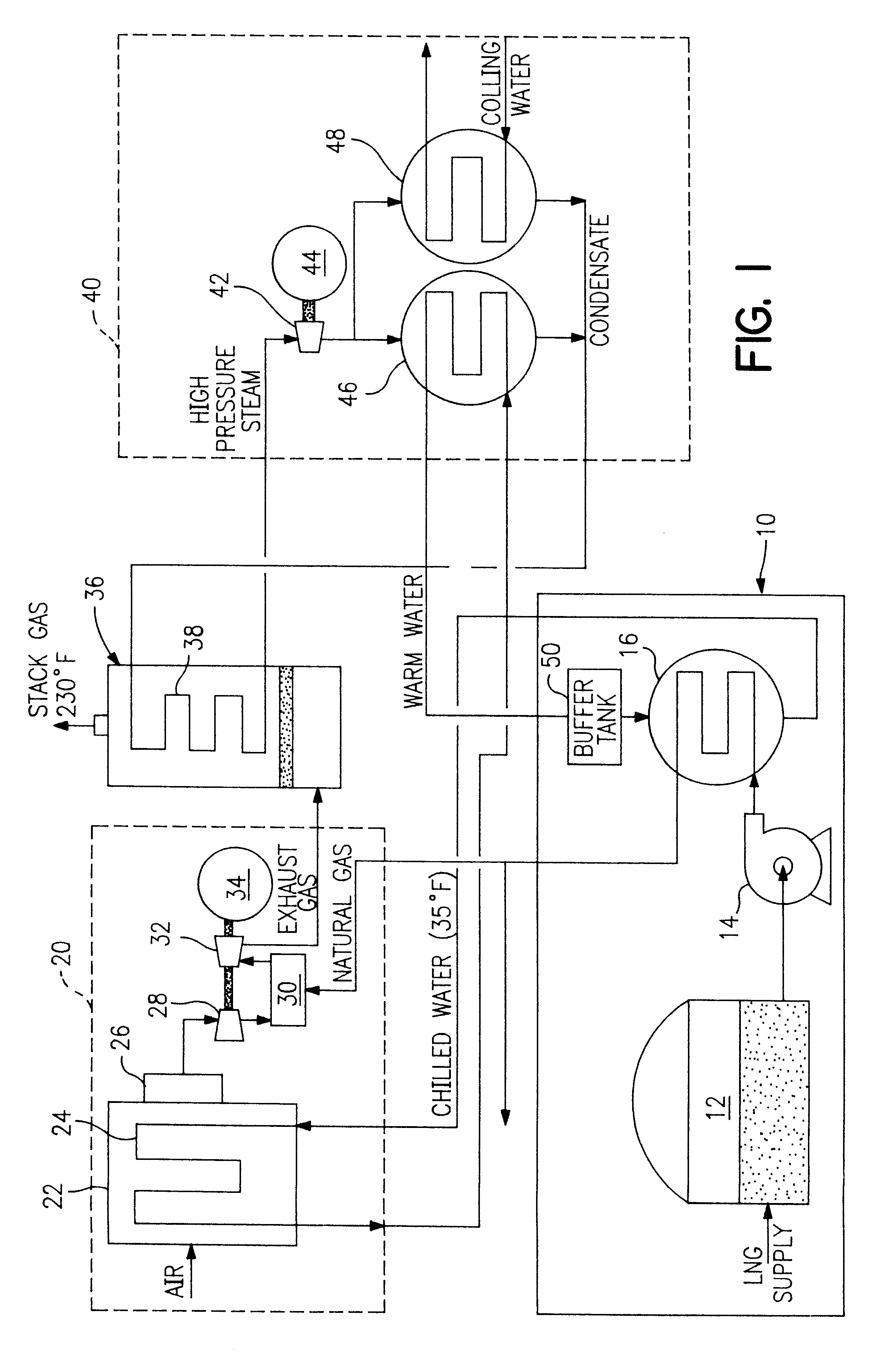
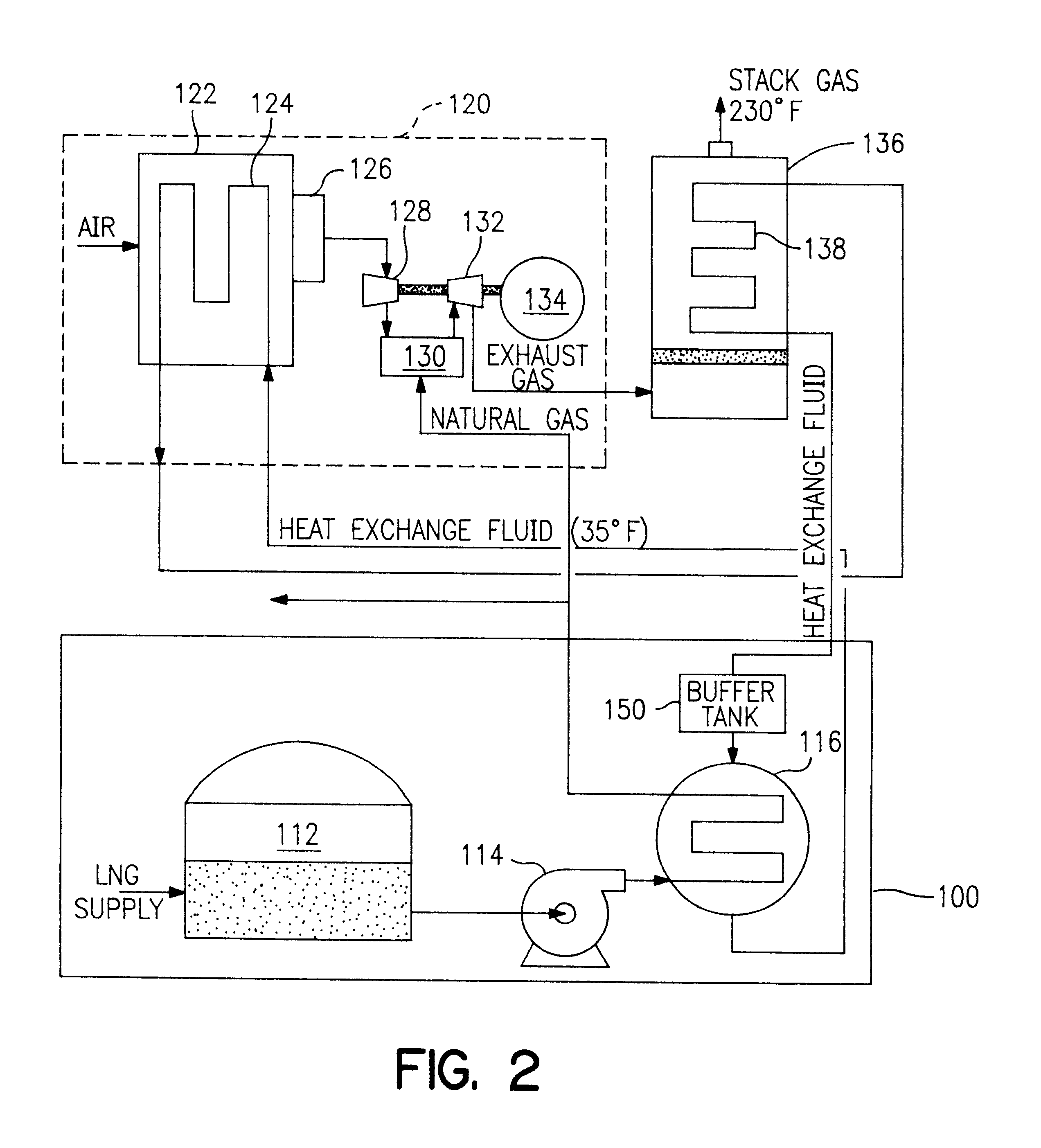
Referring to FIG. 1, a system of one embodiment of the invention comprises a liquefied natural gas (LNG) fuel supply system 10, and a combined cycle power station which comprises a gas turbine plant 20, a steam turbine plant 40 and a waste-heat boiler 36 interposed between the two plants. Circulating pumps for heat exchange fluids are not shown.

The LNG fuel supply system 10 comprises a supply tank 12, a pump 14 and a regasifier / chiller (heat exchanger) 16.

Natural gas from the regasifier / chiller 16 flows to the gas turbine plant 20 and to other power plants and / or to a natural gas distribution system. The gas turbine plant comprises an air intake duct 22, a heat exchanger 24 received therein and a downstream water and particulate filter 26 upstream of an air compressor 28.

Water from the regasifier / chiller 16 in the LNG fuel supply system 10 flows through the heat exchanger 24. The intake air flows across the heat exchanger 24 and is cooled and densified. The cooled densified air flo...


PUM


Abstract

A process and system which improves the capacity and efficiency of a power plant. A LNG supply system fuels the plant. Gasified LNG in a combustor mixes with the air from an air compressor to provide the hot combustion gas for a gas turbine. The expanding LNG is used to chill a heat exchange fluid, e.g. water, which heat exchange fluid cools and densifies the intake air for the air compressor. Subsequently, the heat exchange fluid is used in another heat exchange step and is then re-chilled and recycled to cool and densify the intake air.

Description

The invention relates to the use of LNG in combination with a combined cycle plant (gas turbine plant / steam turbine plant) or a gas turbine plant. The LNG is regasified and chills a heat exchange fluid which fluid is used to cool and densify the intake air for a gas turbine. The heat exchange fluid is then used in one or more heat transfer steps. The regasified LNG is also used as fuel for the gas turbine and optionally for distribution to other power plants and natural gas distribution systems.BACKGROUND AND BRIEF SUMMARY OF THE INVENTIONIt is state of the art practice to extend a gas turbine plant with a waste-heat boiler and to combine the gas turbine plant with a steam turbine plant. The gas turbine and the steam turbine each drive their own generator or drive a single generator via a common shaft. These combination plants, referred to as combined cycle plants, are generally distinguished by their very good conversion efficiencies which range in the order of magnitude from 50 to...

Claims


Application Information

Patent Timeline
Patent Type & Authority Patents(United States)
IPC IPC(8): F01K23/10F02C7/143F02C7/12F17C9/00F17C9/02F01K9/00
CPCF01K23/10F17C9/02F02C7/143F17C2270/0581F17C2265/05Y02E20/18Y02T50/675Y02E20/16F17C2221/033F17C2223/0161F17C2223/033F17C2225/0123F17C2227/0135F17C2227/0316F17C2265/07Y02T50/60
Inventor JOHNSON, PAUL C.TOOMBS, EDWIN
Owner SUEZ LNG NA
Why Eureka
Try Eureka