

Pneumatic tire and method for manufacturing pneumatic tire
a pneumatic tire and pneumatic tire technology, applied in the direction of transportation and packaging, bicycles, other domestic objects, etc., can solve the problems of troublesome application of sealant, difficult to obtain uniform seal layer and pneumatic tire, and complicated production process
Inactive Publication Date: 2003-09-30
SUMITOMO RUBBER IND LTD
View PDF18 Cites 15 Cited by
- Summary
- Abstract
- Description
- Claims
- Application Information
AI Technical Summary
Problems solved by technology
In the former method, however, the step for applying the sealant is troublesome, variations are generated in dimensions of the application, and it is difficult to obtain a uniform seal layer and the uniform tire.
In the latter method, because the injection step for injecting the sealant into the sack-shaped portion d after vulcanization of the tire is necessary and a closing step for closing the injection hole e for injecting the sealant is required additionally, a producing process becomes complicated.
Method used
View moreImage
Smart ImageViewing Examples

Examples
example
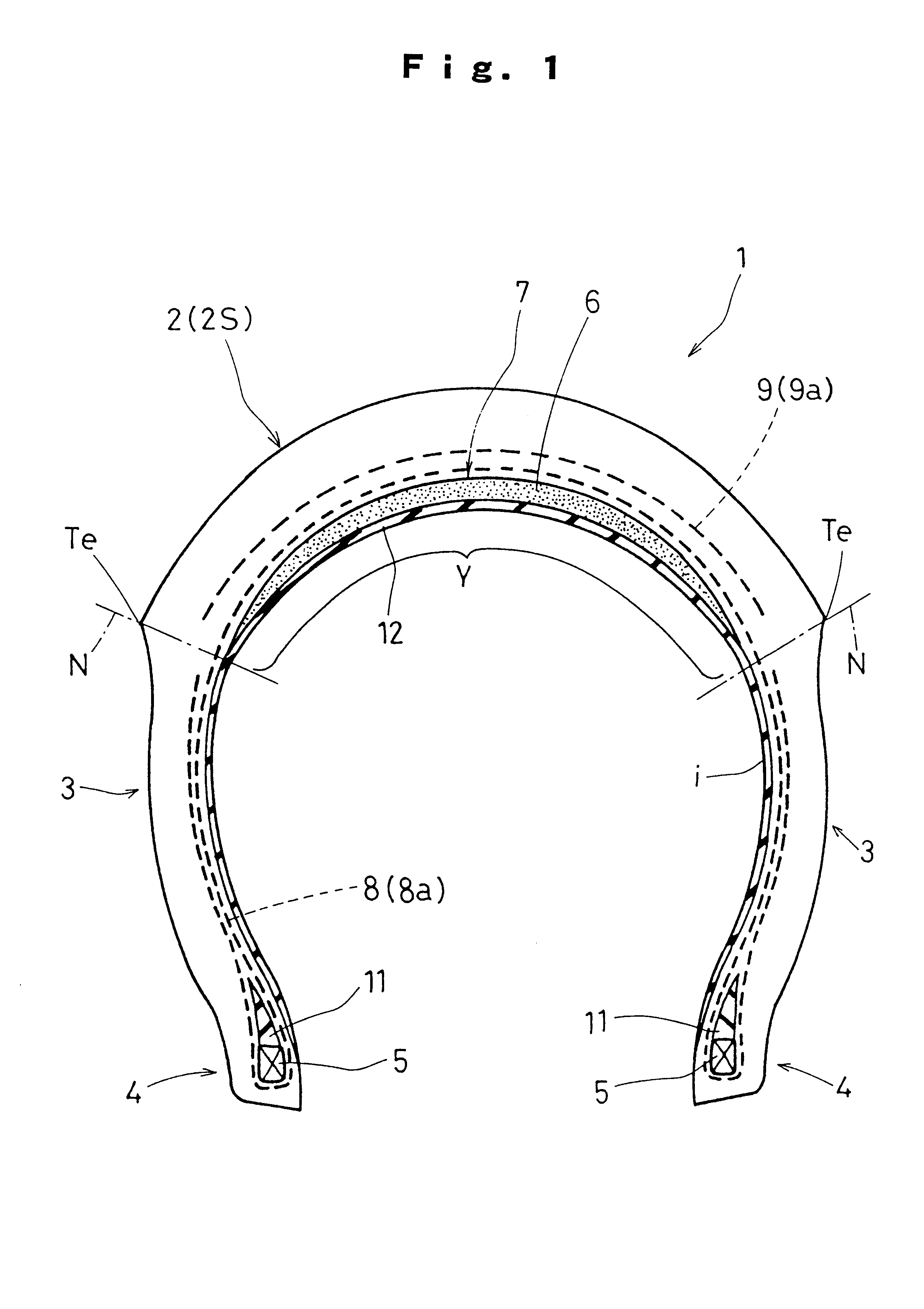
A tire for a motorcycle of a tire size of 3.00-10 was produced for trial according to the above producing method by using a seal unit shown in Table 2 to obtain a satisfactory pneumatic tire shown in FIG. 1. Then, the pneumatic tire was mounted to a rim and inflated. A nail with a diameter of 3 mm was stuck in the tire from a surface side of a tread portion and pulled out. When inner pressure was measured after traveling about 200 km, about 85% or more of the inner pressure before sticking of the nail was maintained and almost no reduction in the inner pressure occurred.
Login to View More PUM
| Property | Measurement | Unit |
|---|---|---|
| temperature | aaaaa | aaaaa |
| angle | aaaaa | aaaaa |
| angle | aaaaa | aaaaa |
Abstract
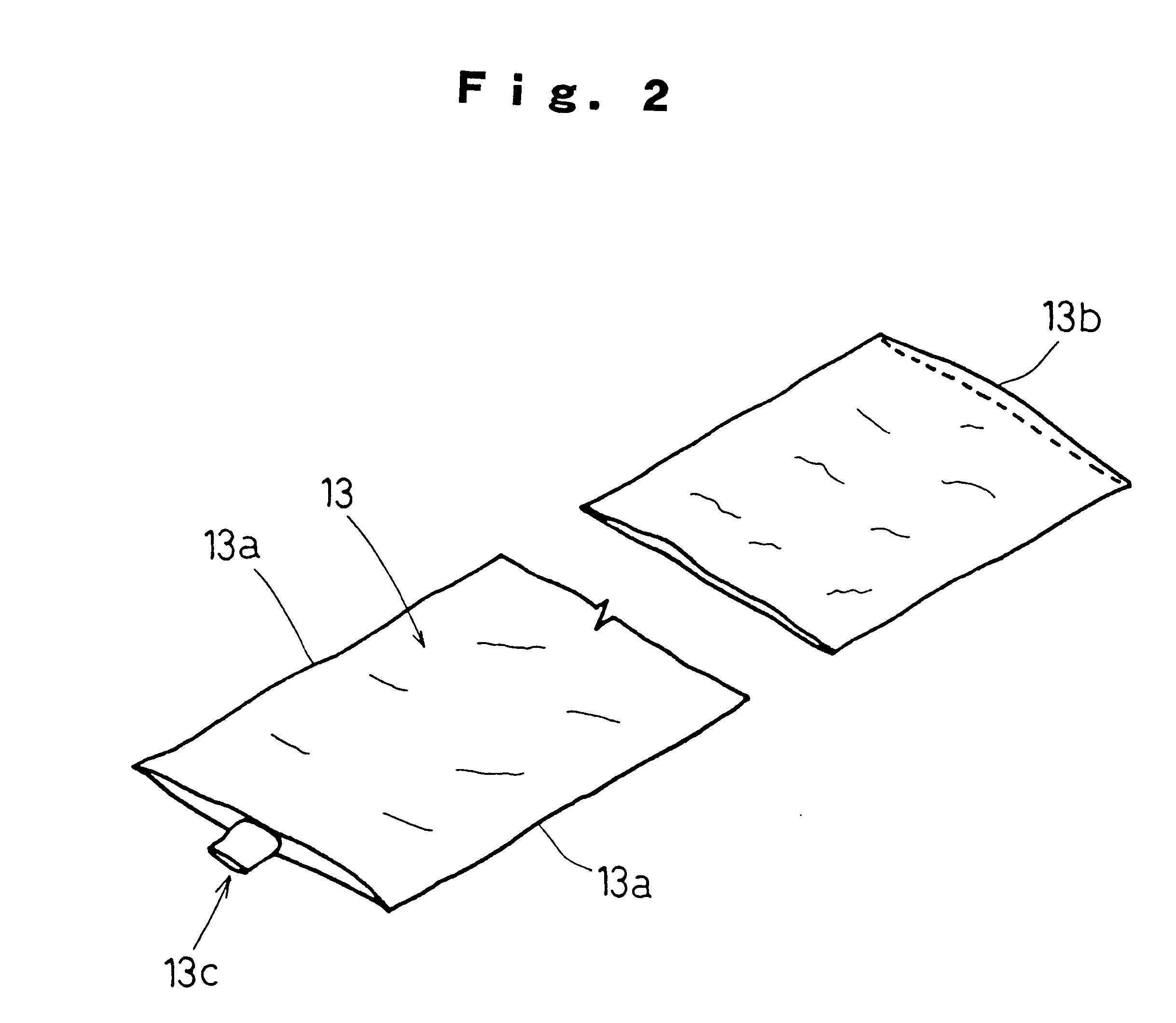
A pneumatic tire 1 having a toroidal shape in which bead portions 4 are connected to sidewall portions 3 extending radially inward from opposite ends of a tread portion 2 and a sealant 6 for preventing a blowout is disposed to extend in a circumferential direction in the tread portion 2. A seal unit 7 formed by sealing the sealant 6 for preventing the blowout in a sack-shaped member in advance is disposed to extend in the circumferential direction of the tire in the tread portion 2 prior to vulcanization.
Description
The present invention relates to a tubeless pneumatic tire in which air leakage from a puncture in a tread due to running over of a nail and the like can be suppressed and a method of producing the same.BACKGROUND TECHNIQUEAs one of means for preventing generation of air leakage from a puncture portion due to running over of a nail and the like, there is proposed a pneumatic tire having a seal layer in which a puncture sealant for sealing a nail puncture and the like is sealed inside a tread.Such a tire can be produced by directly coating an inner liner rubber bonded to a molding former with the sealant, then by bonding a carcass ply and a tread rubber to mold a tire raw cover in a raw cover molding step before vulcanization, and by vulcanizing the tire raw cover.As another method, there is proposed (Japanese Patent Application Laid-open No. 8-323875, for example) a method in which a tire t is vulcanized to form a sack-shaped portion d where inner liner rubber a does not adhere to a...
Claims
Login to View More Application Information
Patent Timeline
 Patent Type & AuthorityPatents(United States)
IPC IPC(8): B29C73/22B29D30/30B29C73/00B60C19/00B60C19/12B60C5/14B29D30/20
CPCB29C73/22B29D30/0685B29D30/30B60C19/12Y10T152/10675B29D2030/0698B29L2030/00B29D2030/069B60C19/122B60C2200/10
InventorOCHIAI, KIYOSHIISHIKAWA, TAKESHI
OwnerSUMITOMO RUBBER IND LTD