Mass storage device mounting system

a technology of mounting system and storage device, which is applied in the direction of electrical apparatus construction details, instruments, casings/cabinets/drawers, etc., can solve the problems of reducing the design flexibility of the data storage system, the speed with which data may be read from or written to an hh device may be slower than the speed with which data may be read from or written to an lp device,

Inactive Publication Date: 2003-09-30
EMC IP HLDG CO LLC
View PDF23 Cites 69 Cited by
  • Summary
  • Abstract
  • Description
  • Claims
  • Application Information

AI Technical Summary

Problems solved by technology

However, the speed with which data may be read from or written to an HH device may be slower than the speed with which data may be read from or written to an LP device.
Thus, in the Assignee's conventional storage system, a single chassis cannot contemporaneously receive and store both LP and HH devices; instead, all of the disk devices stored in a single chassis in the Assignee's conventional storage system must have a single form factor (i.e., LP or HH).
Also unfortunately, since an individual chassis used in the Assignee's conventional data storage system is unable to receive and store disk devices having multiple different form factors, this inherently reduces the design flexibility of the data storage system.

Method used


Image

  • Mass storage device mounting system
  • Mass storage device mounting system
  • Mass storage device mounting system

Examples


Embodiment Construction

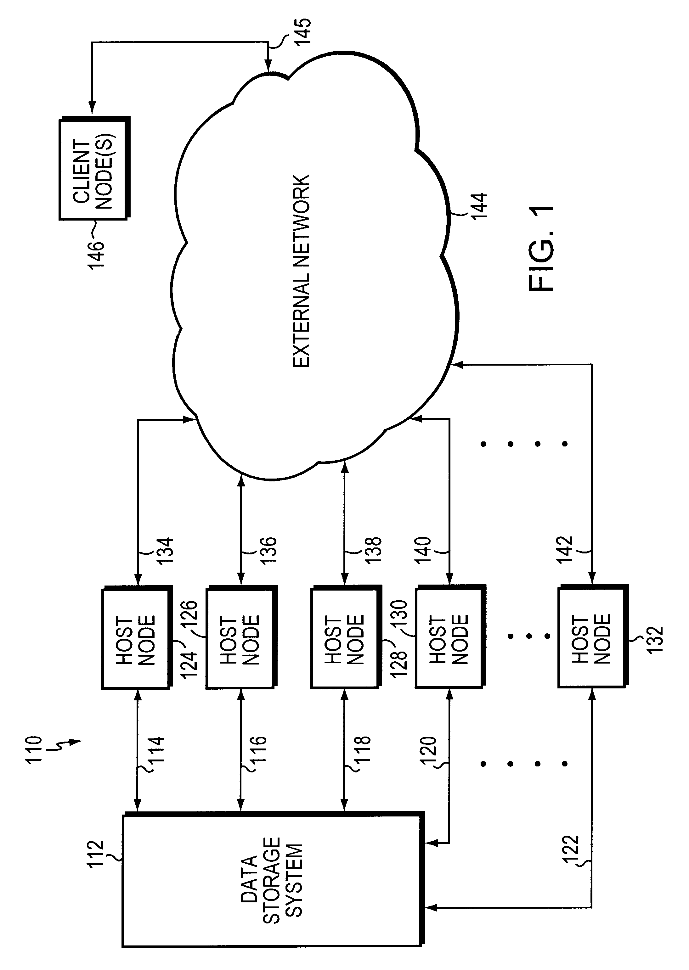
Turning now to FIGS. 1-13, illustrative embodiments of the present invention will be described. FIG. 1 is a high level block diagram illustrating a data storage network 110 that includes a data storage system 112 wherein one embodiment of the subject invention may be practiced to advantage. System 112 is coupled via FC protocol optical communication links 114, 116, 118, 120, . . . 122 to respective host computer nodes 124, 126, 128, 130, . . . 132. Host nodes 124, 126, 128, 130, . . . 132 are also coupled via additional respective conventional network communication links 134, 136, 138, 140, . . . 142 to an external network 144. Network 144 may comprise one or more Transmission Control Protocol / Internet Protocol (TCP / IP)-based and / or Ethernet-based local area and / or wide area networks. Network 144 is also coupled to one or more client computer nodes (collectively or singly referred to by numeral 146 in FIG. 1) via network communication links (collectively referred to by numeral 145 i...


PUM


Abstract

A system is provided that may be used to mount mass storage devices so that they may be used in a mass storage system. The mass storage devices may include respective disk storage devices. Each of the disk storage devices may have a respective form factor that may be a respective one of two possible form factors (e.g., low profile or half-height form factor).

Description

1. Field of the InventionThe present invention relates generally to a system that may be used to mount mass storage devices for use in a mass storage system (e.g., a network mass storage system), and more specifically, to such a mounting system wherein the mass storage devices mounted in the mounting system may comprise disk mass storage devices that have two different form factors.2. Brief Description of Related Prior ArtNetwork computer systems generally include a plurality of geographically separated or distributed computer nodes that are configured to communicate with each other via, and are interconnected by, one or more network communications media. One conventional type of network computer system includes a network storage subsystem that is configured to provide a centralized location in the network at which to store, and from which to retrieve data. Advantageously, by using such a storage subsystem in the network, many of the network's data storage management and control fun...

Claims


Application Information

Patent Timeline
Patent Type & Authority Patents(United States)
IPC IPC(8): G06F1/18
CPCG06F1/184G06F1/187
Inventor GALLAGHER, BRIANTEACHOUT, JEFFREYLINNELL, THOMASWARNAKULASOORIYA, BERNARD
Owner EMC IP HLDG CO LLC
Why Eureka
Try Eureka