
Hinge

a hinge and hinge technology, applied in the field of hinges, can solve the problems of increasing manufacturing costs, affecting the reliability of hinges, and damage to hinges,

Inactive Publication Date: 2003-10-21
NOKIA TECHNOLOGLES OY
View PDF32 Cites 59 Cited by
  • Summary
  • Abstract
  • Description
  • Claims
  • Application Information

AI Technical Summary

Problems solved by technology

Further, the manufacture of a damped hinge using oil / grease as an energy absorber can be difficult and complex, which can increase manufacturing costs and may effect the reliability of the hinge.
Oil / grease can also leak from the hinge, which may not only create a mess but may also affect the dampening performance of the hinge.

Method used


Image

  • Hinge
  • Hinge
  • Hinge

Examples


Embodiment Construction

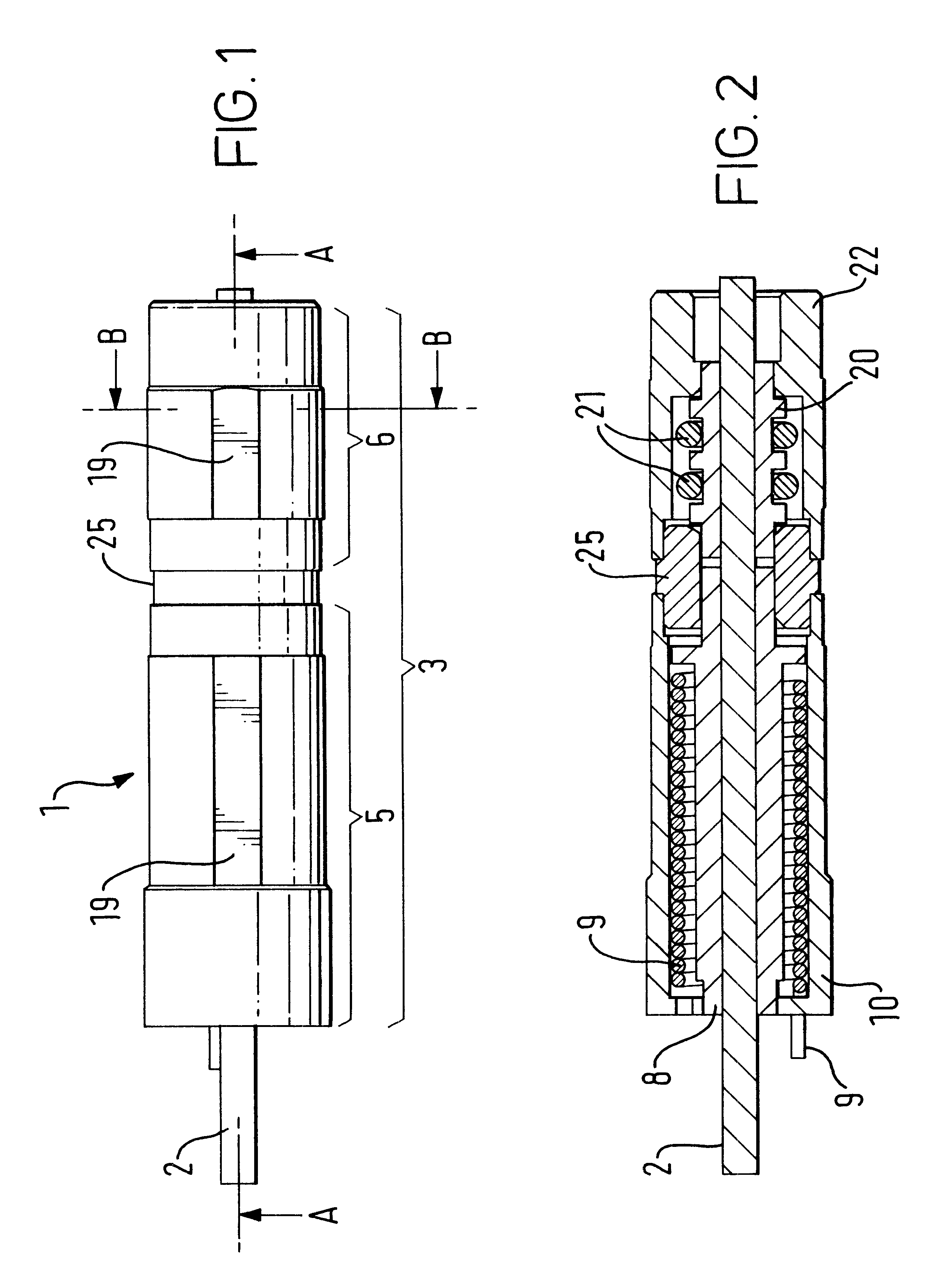
FIG. 1 shows a fully assembled damped hinge 1. The hinge 1 has a central shaft 2 and a cylindrical housing 3. The shaft 2 has a rectangular cross-section, which in this embodiment is used for coupling the hinge 1 to the main housing 4 of a radiotelephone. The cylindrical housing 3 comprises two sections, a biasing section 5 for providing rotational bias and damping section 6 for damping the rotation of the hinge. In this embodiment the cylindrical housing 3 is used for coupling the hinge to a lid 7 of a radiotelephone.

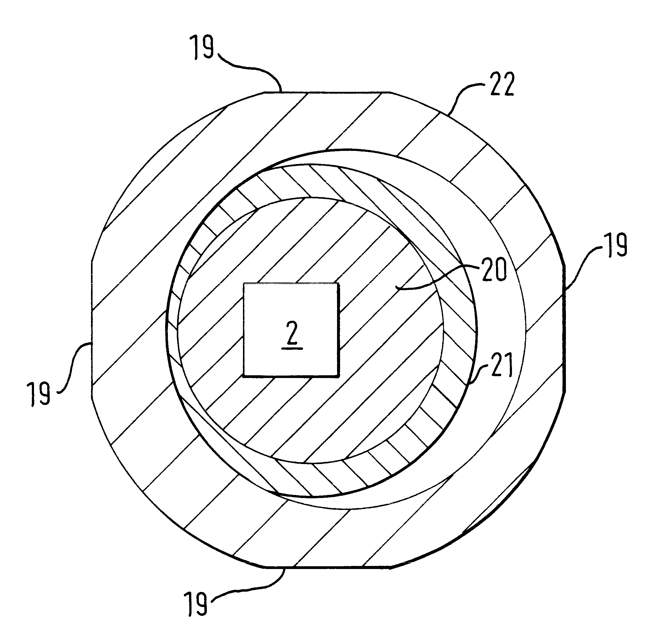
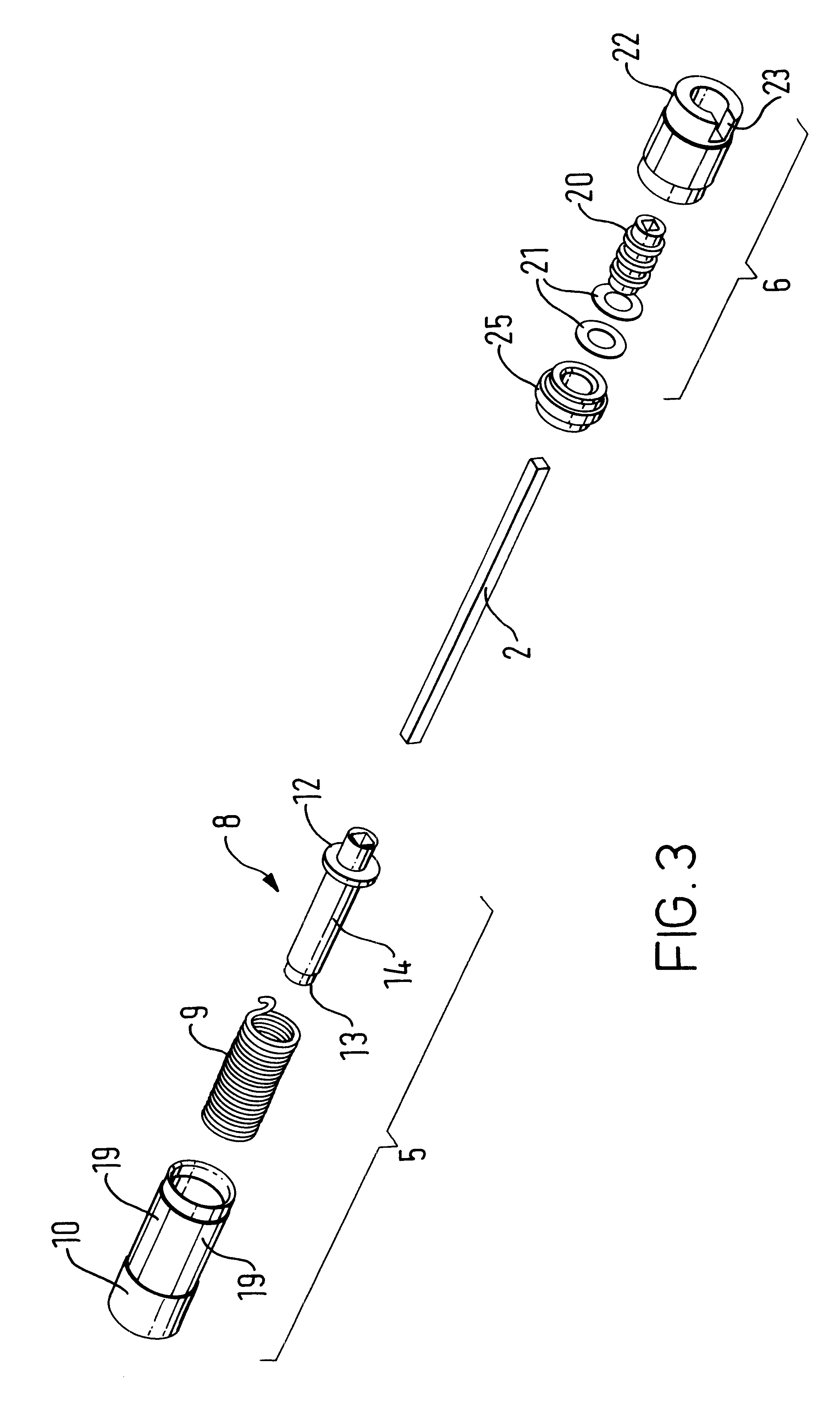
FIG. 2 shows a longitudinal cross-section of the hinge 1 along lines A--A. in FIG. 1. FIG. 3 shows an exploded view of the hinge 1. The biasing section 5 of the cylindrical housing 3 comprises a first cylindrical insert 8, a coiled spring 9 and a first outer cylindrical housing 10. The first cylindrical insert 8 has a rectangular aperture, corresponding in size to the rectangular cross-section of the shaft 2, to allow mounting of the insert 8 on the shaft 2. The apertu...


PUM


Abstract

A damped hinge comprising a first part mounted to a second part to allow relative rotation between the first and second part; biasing means for providing rotational movement between the first and second part; wherein upon rotational movement between the first and second part the first and second parts are arranged to cooperate to dampen the rotational movement.

Description

1. Field of the InventionThis invention relates to a hinge, and in particular a damped hinge.2. Description of the Prior ArtSpring-biased hinges are commonly used in many consumer products for opening lids or doors automatically on release of a latch. Two examples of such products are radiotelephones and cameras. A spring-biased hinge may be used on a radiotelephone to open a flip, where the flip is used to cover the main radiotelephone housing. A spring-biased hinge may be used on a camera to open a lens cover, where the lens cover is used to protect the lens of the camera.Typically the hinge is arranged to couple one element of a device to the main housing of the device such that when the element is closed a latch maintains the element in the closed position with the spring bias of the hinge acting against the latch. When the latch is released the spring bias of the hinge rotates the element way from the main housing.To prevent damage to a device, as a result of a spring-biased hi...

Claims


Application Information

Patent Timeline
IPC IPC(8): E05F1/12E05D11/00E05F1/00E05D11/08H04M1/02
CPCH04M1/0216E05D11/082E05F1/1215E05Y2900/606Y10T16/5403Y10T16/540243Y10T16/54038Y10T16/54E05Y2999/00
Inventor MAYNARD, IAN
Owner NOKIA TECHNOLOGLES OY
Features
  • Generate Ideas
  • Intellectual Property
  • Life Sciences
  • Materials
  • Tech Scout
  • Unparalleled Data Quality
  • Higher Quality Content
  • 60% Fewer Hallucinations
Learn More