Kit for implanting a cementable endoprosthesis

a cementable endoprosthesis and kit technology, applied in the field of kits for cementable endoprostheses, can solve the problems of inexact limited sealing effect of centering and sealing elements, and insufficient centering in the medial-lateral direction of endoprosthesis shaft proximal-distal direction,

Inactive Publication Date: 2003-11-25
PLUS ENDOPROTHETIK AG
View PDF16 Cites 28 Cited by
  • Summary
  • Abstract
  • Description
  • Claims
  • Application Information

AI Technical Summary

Benefits of technology

This embodiment according to the invention has the advantage that the depth of fitting of the endoprosthesis shaft in the medullary cavity of the femur can be adjusted even during implantation. Therefore, it is still possible during implantation to adjust, for example, the length of the femur or depth of fitting of the endoprosthesis shaft in such a way that after the operation has been completed, both legs are the same length. In a preferred embodiment, the kit comprises a manipulating instrument which is inserted into the medullary cavity of the femur before fitting the shaft, in order to determine the optimum depth of fitting, so that in particular an optimum leg length or optimum ligament tensioning is achieved. The optimum depth of fitting which is determined in this way is read off and the endoprosthesis shaft is then inserted into the femur corresponding to this depth of fitting.
The centering and / or sealing element has, in the proximal direction, an end face which is advantageously used as a reference surface. The centering and / or sealing element is preferably inserted into the medullary cavity in such a way that said reference surface is flush with the resected surface of the femoral neck. The endoprosthesis shaft is secured on a fitting instrument prior to insertion, a spacer element additionally being secured on the fitting instrument, said spacer element being designed in such a way that with the endoprosthesis shaft inserted deep in the medullary cavity, it lies on the reference surface of the centering and / or sealing element and prevents any further insertion of the shaft. By means of this spacer element which is available in different sizes, the depth of fitting of the endoprosthesis shaft can be adjusted exactly with respect to the resected surface. A spacer element corresponding to the desired depth of fitting is chosen and is secured on the fitting instrument prior to insertion of the endoprosthesis shaft.

Problems solved by technology

This known combination of endoprosthesis shaft and suitably adapted centering and sealing element has the disadvantage that the depth of insertion of the endoprosthesis shaft in the medullary cavity of the femur in the proximal-distal direction can be set only with difficulty and therefore inexactly.
In addition, the centering and sealing element has only a limited sealing effect and inadequate centering in the medial-lateral direction.

Method used


Image

  • Kit for implanting a cementable endoprosthesis
  • Kit for implanting a cementable endoprosthesis
  • Kit for implanting a cementable endoprosthesis

Examples


Embodiment Construction

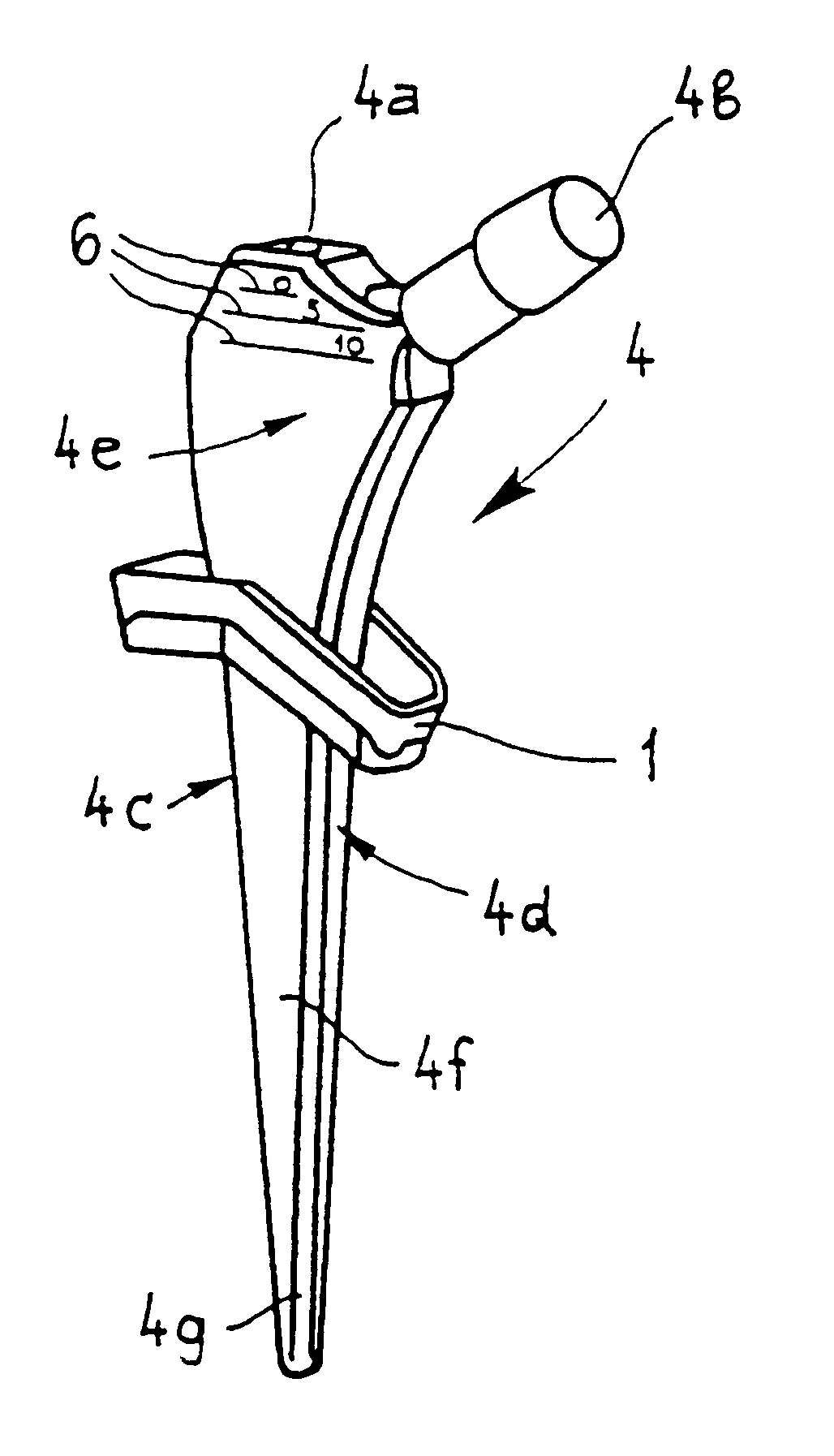
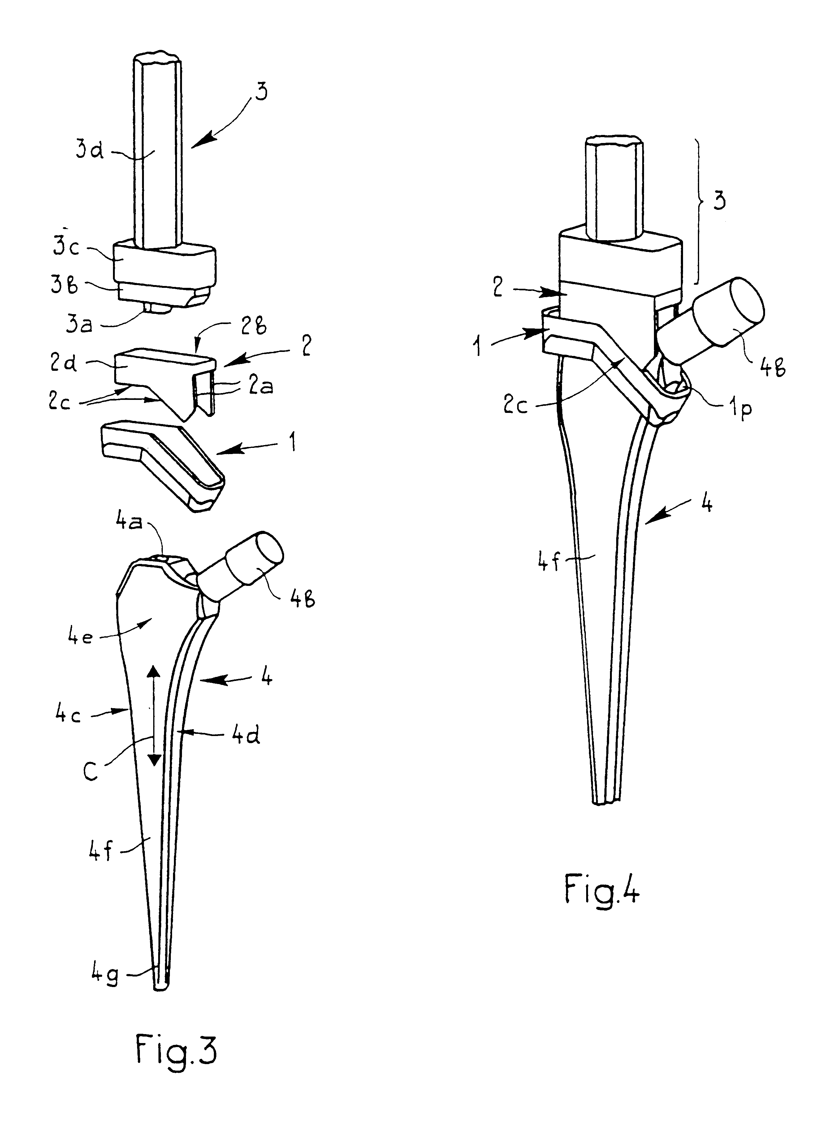
FIG. 3 shows an illustrative embodiment of a kit according to the invention, comprising an endoprosthesis shaft 4 which is designed as a straight shaft, the actual shaft 4f having an essentially rectangular cross section with two narrow-side surfaces 4c, 4d and two broad-side surfaces 4e. At the proximal end, the shaft 4f has an internal thread 4a and a cone 4b for a joint head. The kit further comprises a fitting instrument 3 which has a connection rod 3d on which a stamp 3c is secured which opens into an adapter piece 3b and an external thread 3a. The kit further comprises a spacer element 2 which is designed as a sleeve-shaped, rectangular body 2d, with two side wings 2a which form an upper limit stop surface 2b and a lower limit stop surface 2c. The kit also comprises a proximal centering and / or sealing element 1. The spacer element 2 is designed in such a way that it lies with its upper limit stop surface 2b on the stamp 3c. Upon insertion of the endoprosthesis shaft 4, the low...


PUM

PropertyMeasurementUnit
depth of fittingaaaaaaaaaa
depth of insertionaaaaaaaaaa
insertion depthaaaaaaaaaa

Abstract

The kit for implanting a cementable endoprosthesis includes a fitting instrument and at least two components to be implanted, namely an endoprosthesis shaft and a proximal centering and / or sealing element, the shaft and the fitting instrument being designed to be able to be coupled to each other, and the centering and / or sealing element being designed to be placeable on the shaft and to be displaceable in the direction of extension of the latter, and either the fitting instrument including a limit stop part which forms a limit stop relative to the centering and / or sealing element, or a marking being arranged on the fitting instrument and on the shaft in order to ensure a defined mutual position between the centering and / or sealing element and the shaft.

Description

1. Field of the InventionThe invention relates to a kit for implanting a cementable endoprosthesis.2. Description of Related ArtDocument DE 195 18 391 A1 discloses a proximal centering and sealing element for implanting a cementable endoprosthesis shaft, which element on the one hand serves as a proximal centering aid and on the other hand prevents escape of the cement in the proximal direction, as a result of which, when inserting the endoprosthesis shaft into the medullary cavity, there is an increase in the pressure of the bone cement located therein.This known combination of endoprosthesis shaft and suitably adapted centering and sealing element has the disadvantage that the depth of insertion of the endoprosthesis shaft in the medullary cavity of the femur in the proximal-distal direction can be set only with difficulty and therefore inexactly. In addition, the centering and sealing element has only a limited sealing effect and inadequate centering in the medial-lateral directi...

Claims


Application Information

Patent Timeline
Patent Type & Authority Patents(United States)
IPC IPC(8): A61F2/30A61F2/36A61F2/46A61B17/16A61F2/00A61B17/58A61F
CPCA61F2/30724A61F2/30734A61F2/367A61F2/4607A61F2/4657A61B17/1659A61F2310/00952A61F2/36A61F2/4684A61F2002/30153A61F2002/30332A61F2002/30616A61F2002/30617A61F2002/30738A61F2002/30797A61F2002/365A61F2002/4631A61F2002/4662A61F2220/0033A61F2230/0019A61F2250/0097A61F2310/00023A61F2310/00353A61F2310/00407A61B17/8808
Inventor SCHMOTZER, HANSHASSIG, CHRISTOPH
Owner PLUS ENDOPROTHETIK AG
Why Eureka
Try Eureka