Switching mechanism and electric switch using the same

a technology of switching mechanism and electric switch, which is applied in the direction of contact mechanism, snap-action arrangement, contacts, etc., can solve the problems of spring-reversal type of electric switch, liable to allow the contact to bounce, and badly worn or deformed

Inactive Publication Date: 2003-12-16
SATORI ELECTRIC
View PDF9 Cites 15 Cited by
  • Summary
  • Abstract
  • Description
  • Claims
  • Application Information

AI Technical Summary

Problems solved by technology

Spring-reversal type of electric switches, however are liable to allow their contacts to bounce at the time of turning on and off.
Thus, the contacts will be badly worn or deformed and accordingly the life of the electric switches will be shortened.
The contact-making mechanism, however, is liable to reduce drastically its contact pressure just prior to the reversing action, which is caused by the push spring.
If the electric switch should be shaken at the instant of the contact pressure being reduced, arks are liable to appear with the result that the contacts are badly worn or deformed.
Therefore, electric switches having the same switching characteristics can hardly be reproduced.

Method used


Image

  • Switching mechanism and electric switch using the same
  • Switching mechanism and electric switch using the same
  • Switching mechanism and electric switch using the same

Examples


Embodiment Construction

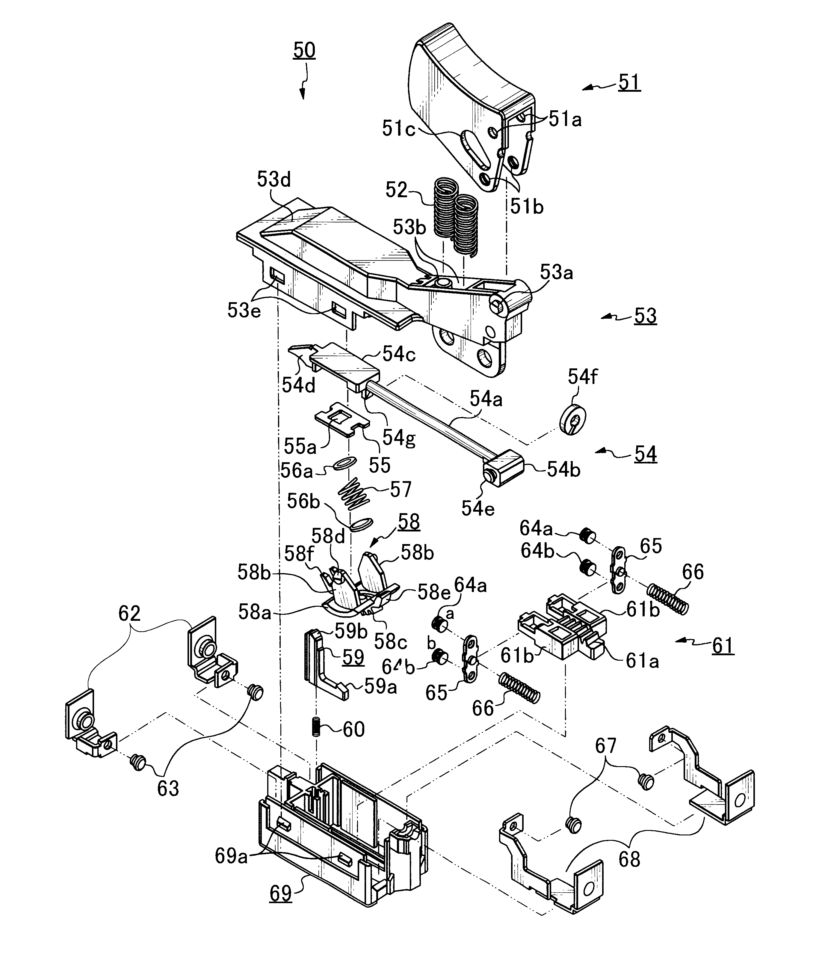
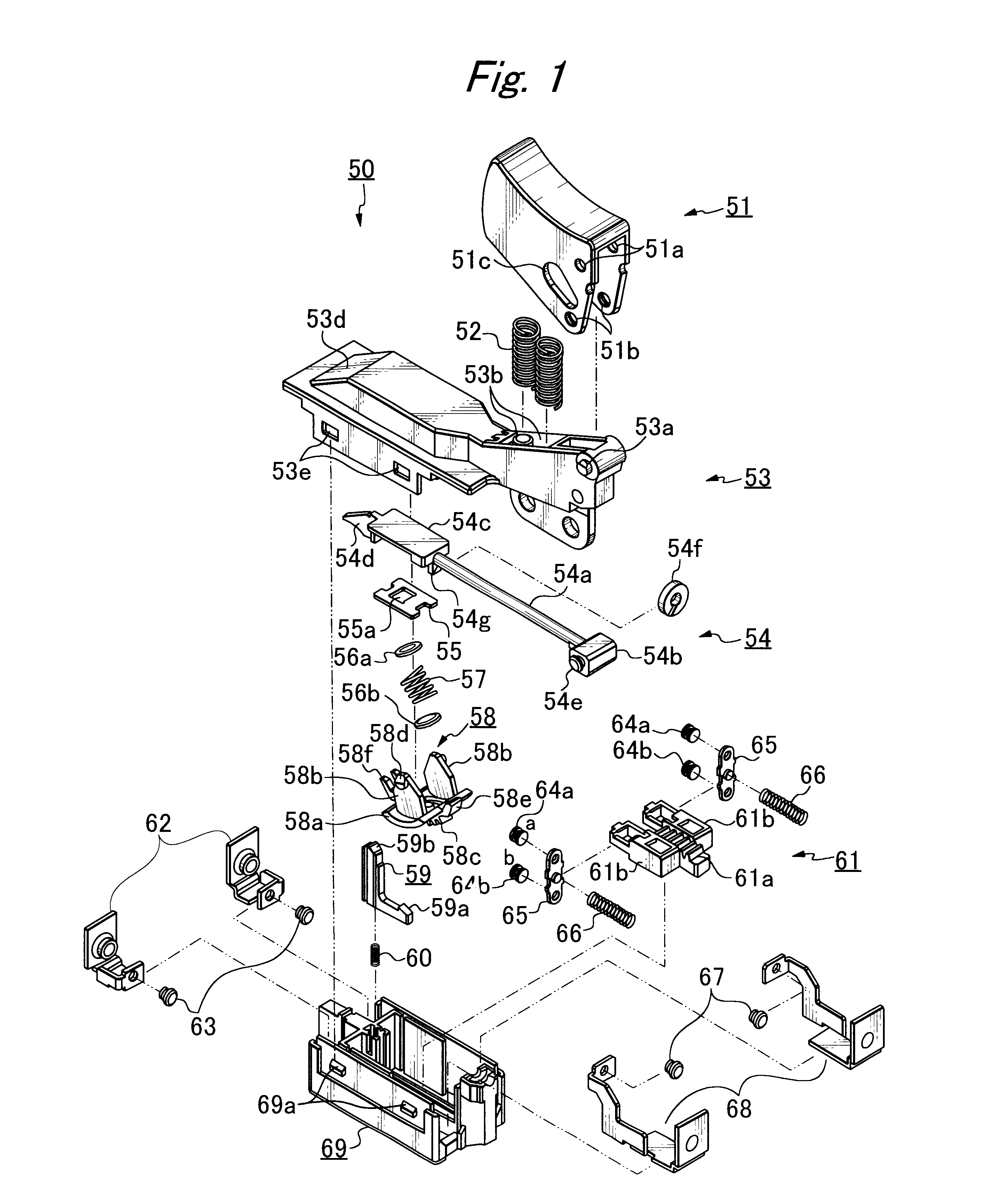
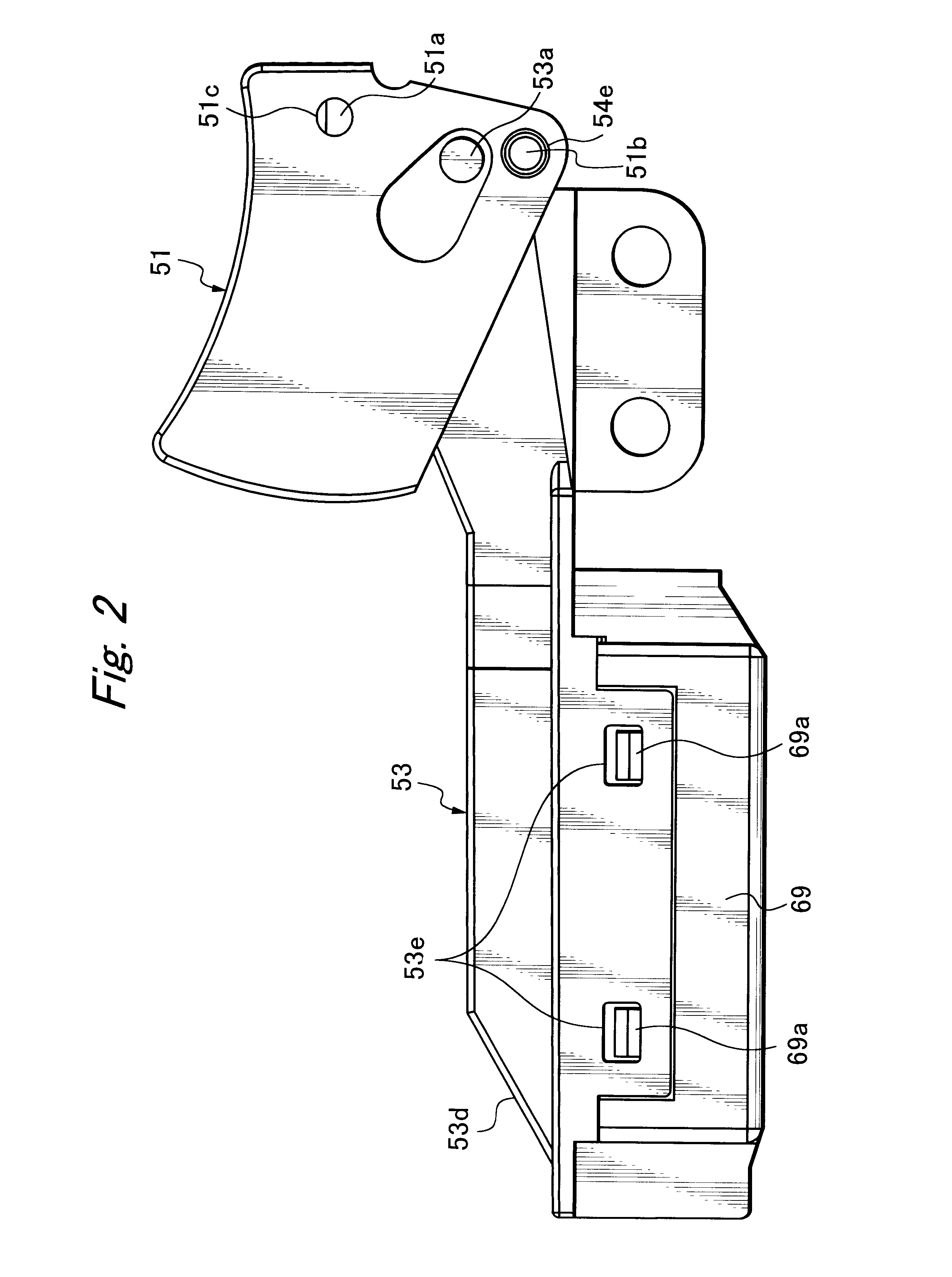
A switching mechanism and an electric switch using the same according to one embodiment of the present invention are described below. In the drawings the left sides of the drawings corresponds to the front side of the electric switch and the right sides of the drawings corresponds to the rear side of the electric switch. The electric switch is equipped with the switching mechanism, and therefore, the electric switch is described by describing the switching mechanism only.

As seen from FIG. 1, a spring-reversal type of electric switch 50 equipped with a switching mechanism according to the present invention comprises an operating lever 51, two return springs 52, a cover 53, a plunger 54, a guide plate 55, upper and lower disks 56a and 56b, a reversal spring 57, a reversal member 58, an L-shaped stopper 59, a stopper spring 60, an actuator 61, two terminals 62, two stationary contacts 63, four movable contacts 64a, 64b, two movable pieces 65, two compression springs 66, two stationary ...


PUM


Abstract

An AC / DC switch for electric power tools avoids bouncing when turned on, but assures quick cutting-off of heavy current. Operation does not vary with age, as might be caused by wearing of projections of the switching mechanism and / or inconsistency in spring material. A reversal spring quickly switches the mechanism on and off so that the movable contacts are brought close to the stationary contacts before the turning-on, thereby permitting the turning-on subsequent to traverse of the reversal point without bouncing of the movable contacts from the stationary contacts, and preventing movement of the movable contacts before reversal spring has stored increased energy, thus allowing quick release of stored energy to make the movable contacts leave the stationary contacts at a speed sufficient to prevent electric arcs between the movable and stationary contacts, and hence prevent the wearing of the contacts.

Description

1. Field of the InventionThe present invention relates to a switching mechanism and an electric switch, and more particularly to a switching mechanism for a spring-reversal type of electric switch appropriate for use in electric power tools.2. Related ArtsSpring-reversal type of electric switches are used in electric power tools for closing and opening their circuits in which heavy current flows. Such spring-reversal type of electric switches give a pleasing click feeling to users at the time of turning on and off, and the quick "on" and "off" switching action is appropriate for closing and opening circuits in which heavy currents flow. Also, spring-reversal type of electric switches can be used commonly for AC and DC.Spring-reversal type of electric switches, however are liable to allow their contacts to bounce at the time of turning on and off. Particularly at the time of turning "on" a rush current flows, thereby making it easy for arcs to appear across confronting contacts as a ...

Claims


Application Information

Patent Timeline
Patent Type & Authority Patents(United States)
IPC IPC(8): H01H1/50H01H1/00H01H9/06H01H9/02H01H15/18H01H15/00H01H5/00H01H5/06H01H3/00H01H19/635H01H19/00H01H5/10H01H9/20
CPCH01H1/50H01H15/18H01H9/06H01H3/001H01H5/06H01H2300/048H01H19/635
Inventor KATO, YUICHI
Owner SATORI ELECTRIC
Why Eureka
Try Eureka