
Ganged receptacle fixture apparatus

a fixture and receptacle technology, applied in the direction of protective switch terminal/connection, coupling device connection, tumbler/rocker switch, etc., can solve the problems of limited space within the enclosure, substantial hand work, and limited space in the enclosur

Inactive Publication Date: 2003-12-23
NORVELLE ROBERT D
View PDF18 Cites 35 Cited by
  • Summary
  • Abstract
  • Description
  • Claims
  • Application Information

AI Technical Summary

Problems solved by technology

Due to limited enclosure space, and as will be appreciated by one familiar with such mounting procedures, substantial hand work is required to connect the enclosure source wiring with a receptacle or switch module.
The space within a given enclosure becomes even more limited due to the need to coil excess supply-side wire within the receptacle or outlet box behind the individual module.
The addition of one or more jumper wires significantly decreases the room available in the enclosure, thus increasing the difficulty in installation of the supply wires to the source module.

Method used


Image

  • Ganged receptacle fixture apparatus
  • Ganged receptacle fixture apparatus
  • Ganged receptacle fixture apparatus

Examples


Embodiment Construction

This invention is described in a preferred embodiment in the following description with reference to the figures. While this invention is described in terms of the best mode for achieving this invention's objectives, it will be appreciated by those skilled in the art that variations may be accomplished in view of these teachings without deviating from the spirit or scope of the present invention.

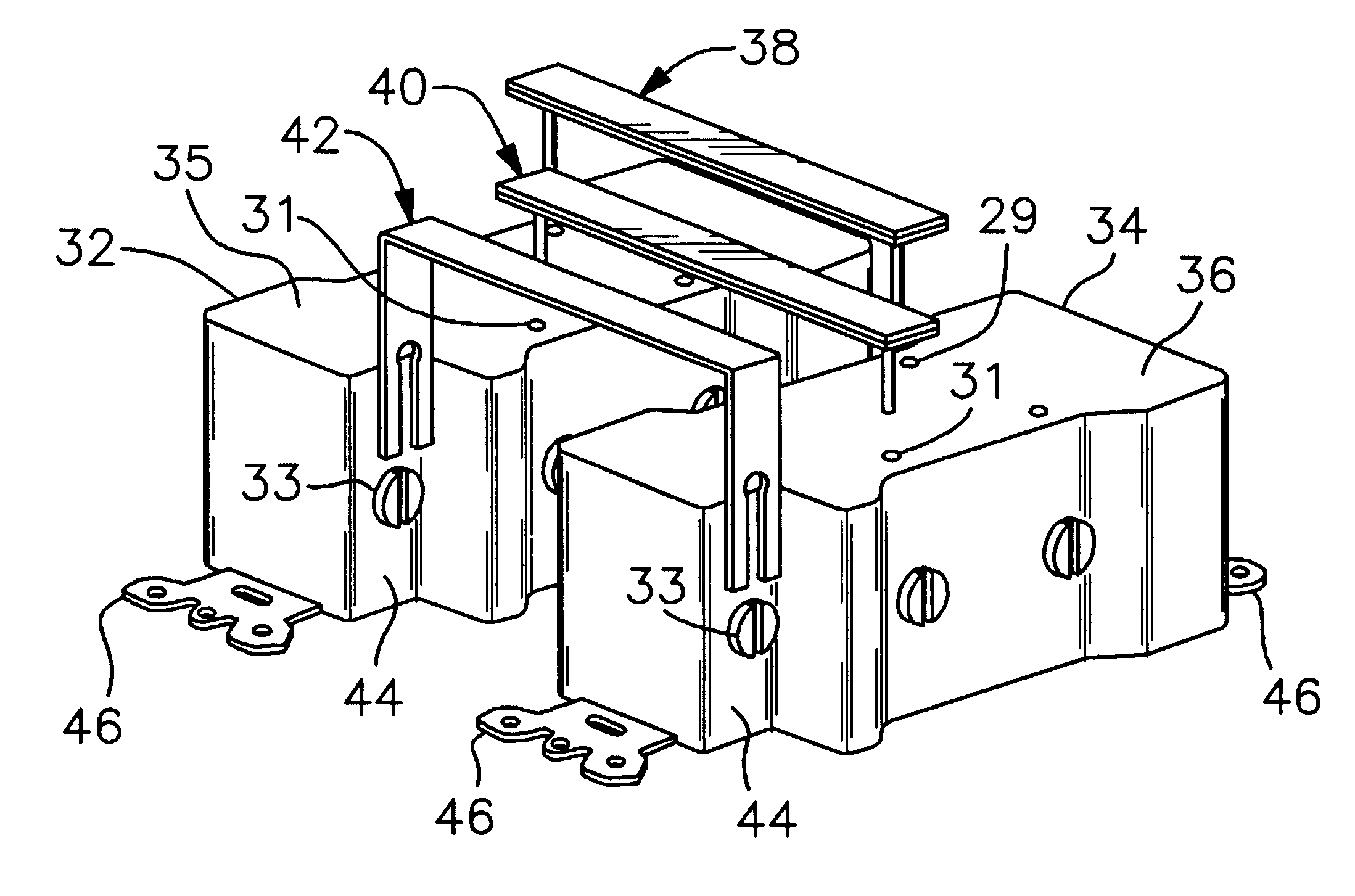
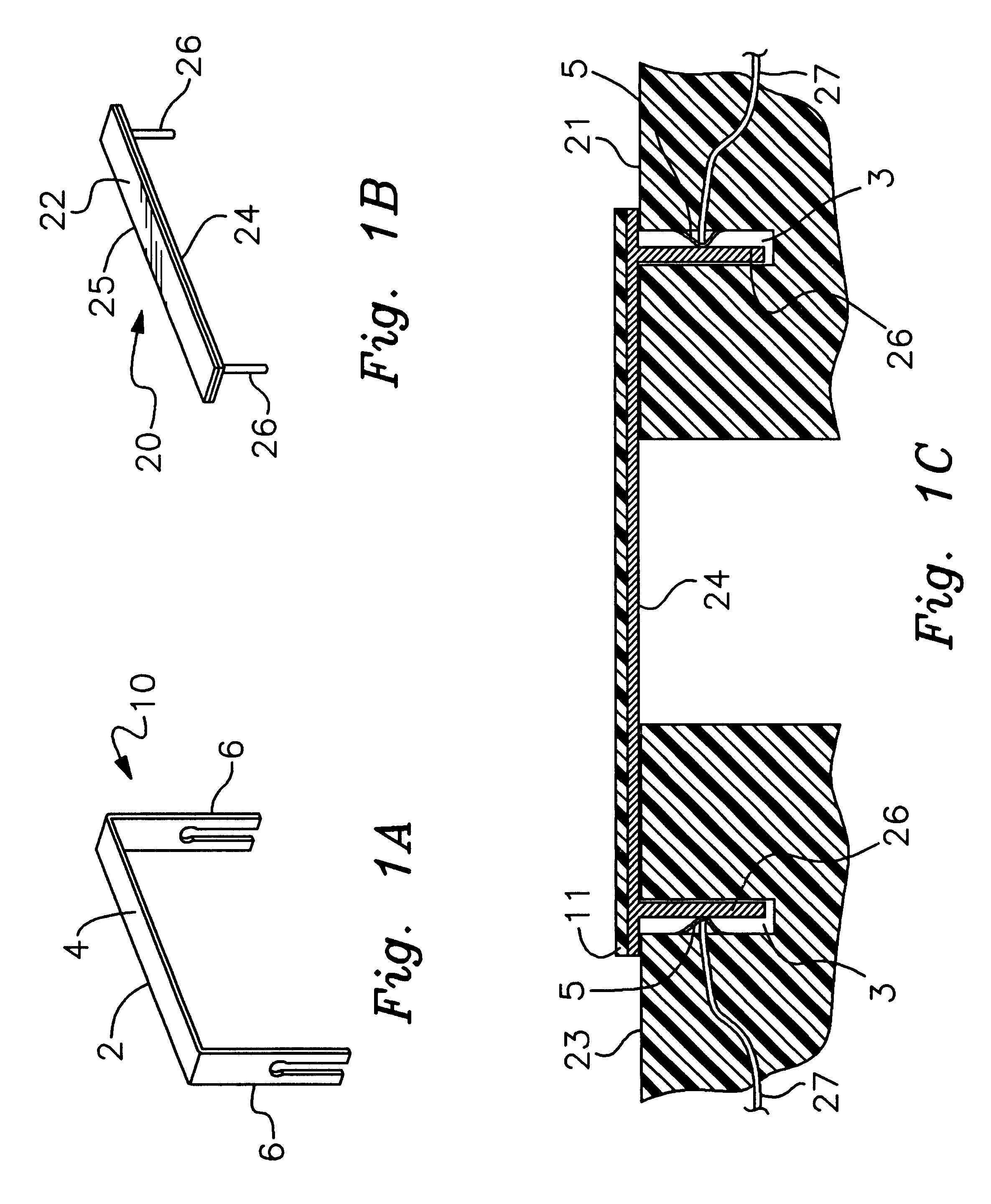
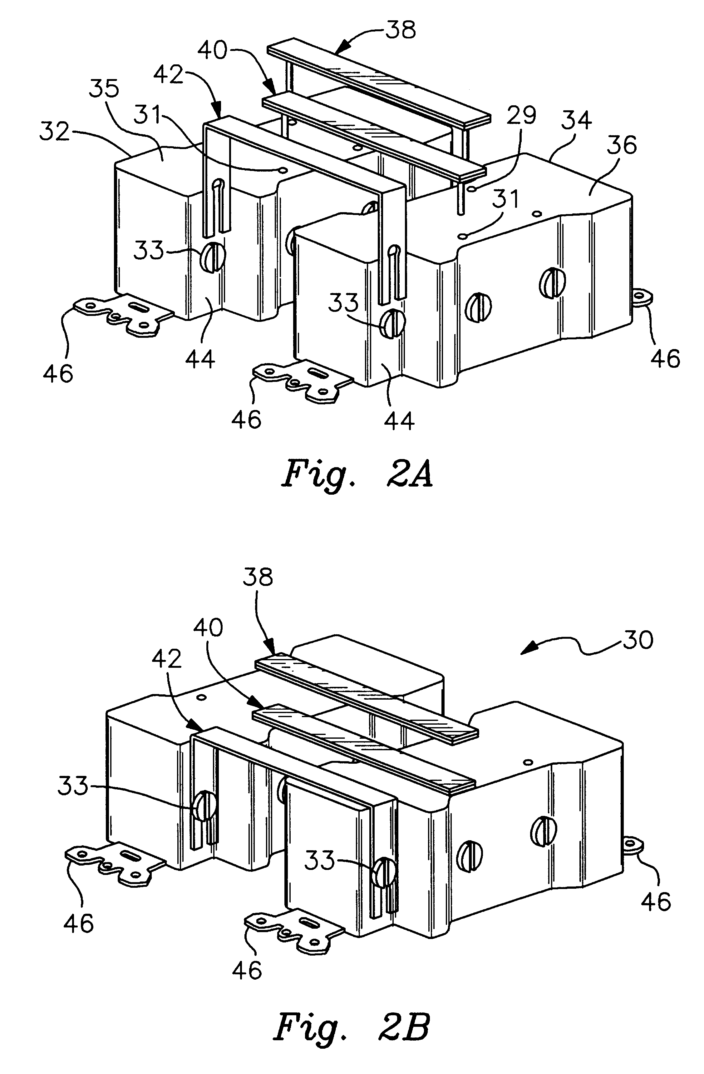
The present invention is directed to a gang bus apparatus that provides electrical contact between multiple plug receptacle outlets or fixture switches, while simultaneously providing a rigid mutual coupling of the modules for convenient mounting within a confined receptacle enclosure. As explained herein, the gang bus apparatus of the present invention improves upon conventional jumper wire connectivity by a flat bar design that results in maximizing the space available within a given enclosure and dispensing with the need to manually adjust the mutual positioning of fixture modules within ...


PUM


Abstract

A gang bus apparatus for rigidly coupling plug receptacles within a receptacle enclosure. In accordance with one embodiment of the present invention, a gang bus apparatus includes at least two discrete plug receptacle modules. Each of the plug receptacle modules includes a front surface disposed substantially co-planar with an opening of a module enclosure, the front surface including electromechanical plug reception means for mating with an electrical plug. Each of the plug receptacle modules further includes an opposing rear surface having at least one electromechanical contact point. A rigid, substantially flat conductive bar is disposed along the rear surfaces of the at least two plug receptacles with the conductive bar coupled to each of the electromechanical contact points to simultaneously provide a rigid structural connection between the plug receptacles and provide a common electrical node between the electromechanical contact points.

Description

1. Technical FieldThe present invention relates in general to electrical receptacles and switches encased within receptacle enclosures, and in particular to joining multiple receptacles or switches within an enclosure. More particularly, the present invention relates to a gang bus suitably constructed, and disposed between two or more receptacles or switches within a confined receptacle enclosure.2. Description of the Related ArtElectrical power is typically supplied to a building from external power lines into a centralized power panel. From the power panel, the supply power is distributed throughout the structure or building by the positioning of outlet or wall enclosures utilized as terminal access points for the power supply system. Such outlet enclosures are typically cavities extending behind the outer surface of a wall having dimensions suitable for retention of electrical receptacles or switches, depending on the application. A receptacle is a static forum for manually coupl...

Claims


Application Information

Patent Timeline
Patent Type & Authority Patents(United States)
IPC IPC(8): H01H71/08H01R31/08H01R4/28H01R31/00H01R4/34
CPCH01H71/082H01R31/08H01R4/34
Inventor NORVELLE, RONALD D.
Owner NORVELLE ROBERT D
Learn More