Determining adjustment value for recording position deviation at printing using a plurality of kinds of inspecting patterns

a technology of recording position deviation and adjustment value, which is applied in the direction of printing mechanism, spacing mechanism, printing, etc., can solve the problems of difficult to reduce such graininess in printed images, and printed images sometimes become grainy in color printing

Inactive Publication Date: 2004-01-06
SEIKO EPSON CORP
View PDF9 Cites 17 Cited by
  • Summary
  • Abstract
  • Description
  • Claims
  • Application Information

AI Technical Summary

Benefits of technology

Aimed at partially addressing the above-described problems, the present invention entails setting an adjustment value designed to reduce dot formation misalignments in a direction of main scanning during a process in which a printing device provided with a plurality of monochromatic nozzle groups for ejecting ink drops having mutually different colors is used to print images by depositing ink drops on a print medium and to form dots while main scanning is performed to move the plurality of monochromatic nozzle groups and / or the print medium. For the printing, a plurality of first color patches are formed on a print medium with dots composed of two or more types of ink for a plurality of auxiliary adjustment values, respectively. The plurality of first color patches are designed to reproduce mutually identical colors. A second color patch is formed on a print medium using dots composed of two or more types of ink in a different color and / or different method from that of the plurality of first color patches. The adjustment value is selected from the plurality of auxiliary adjustment values on the basis of the plurality of first color patches and the second color patch. Adopting this approach makes it possible to set an adjustment value after comparing the graininess of color patches that differ in color and / or printing scheme. As a result, it is possible to adjust recording position misalignments in the direction of main scanning and to reduce the graininess of images printed in color.
The second color patch is preferably formed on the print medium by a printing scheme different from that adopted for the plurality of first color patches, when the second color patch is formed. The second color patch reproduces the same color as that adopted for the plurality of first color patches. Adopting this approach makes it easier to select an adjustment value capable of yielding higher quality during printing by various printing schemes because a color patch with the same reproduction color is printed using a different printing scheme.
The plurality of first color patches are preferably formed by bidirectional printing, when the first color patch is formed. The second color patch is preferably formed by unidirectional printing, when the second color patch is formed. A dot formation misalignment brought about by bidirectional printing does not appear during unidirectional printing. With this arrangement, therefore, a first color patch in which bidirectional printing induces only a minimal dot formation misalignment can be easily selected by comparing a first color patch obtained by bidirectional printing and a second color patch obtained by unidirectional printing.
It is preferable that gray is selected as a color of the plurality of first color patches and the second color patch. Adopting this arrangement allows adjustment values to be set by conducting a comprehensive assessment of the effect of dot misalignments affecting on the color inks used for color printing.

Problems solved by technology

However, though making straight lines less jaggy, printed images sometimes become grainy in color printing due to minute misalignments affecting dots of various colors.
It has so far been difficult to reduce such graininess in printed images with the aid of conventional correction methods.

Method used


Image

  • Determining adjustment value for recording position deviation at printing using a plurality of kinds of inspecting patterns
  • Determining adjustment value for recording position deviation at printing using a plurality of kinds of inspecting patterns
  • Determining adjustment value for recording position deviation at printing using a plurality of kinds of inspecting patterns

Examples


first working example

D. First Working Example

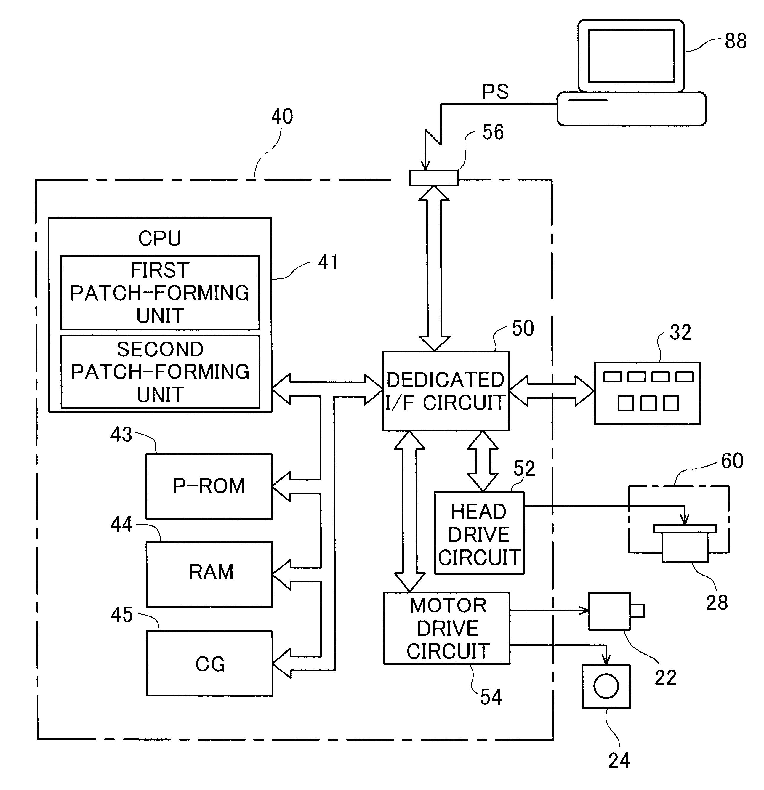
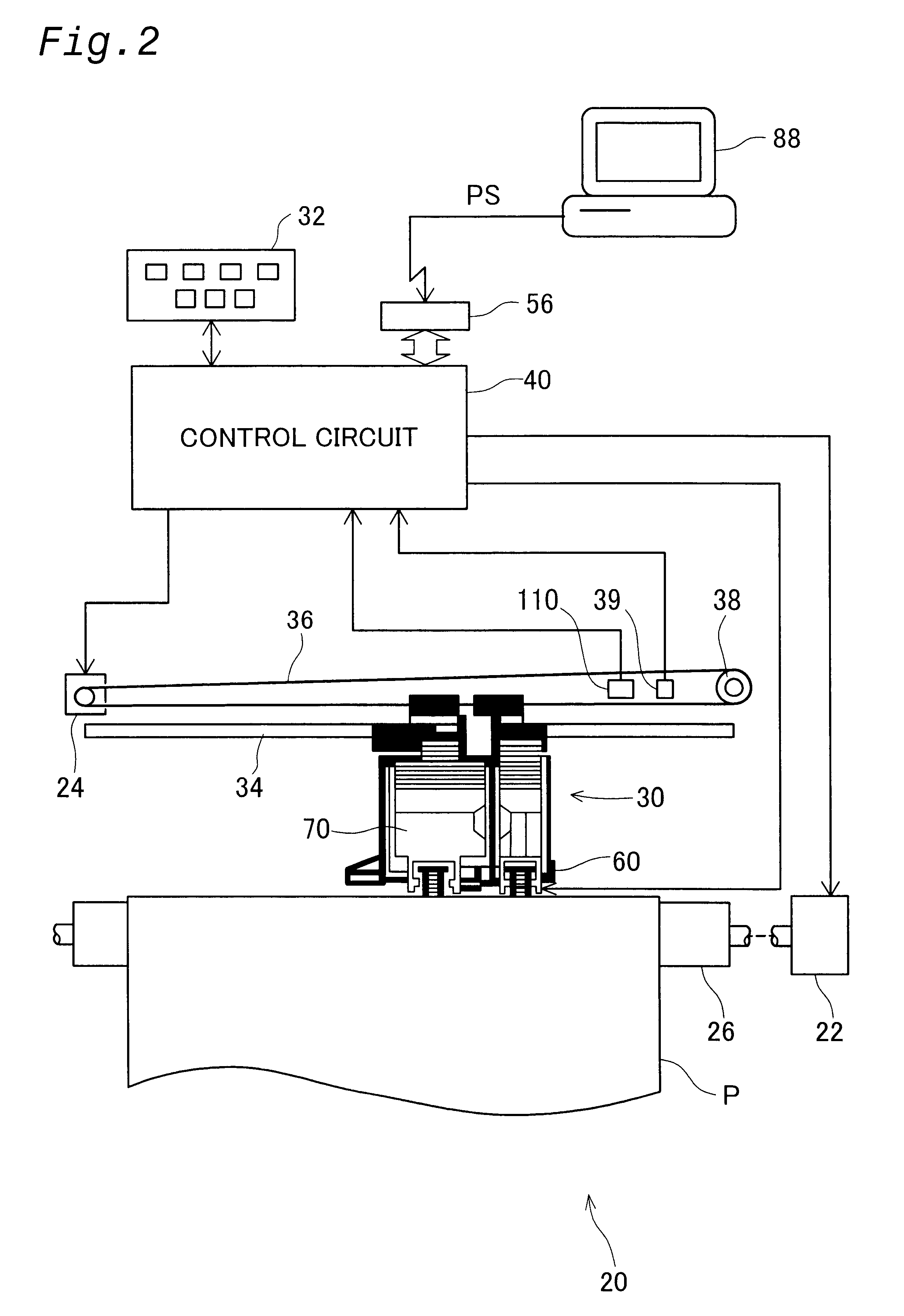
FIG. 6 is a flowchart depicting the entire routine performed in accordance with the first working example of the present invention. In step S1, a first misalignment verification pattern and a second misalignment verification pattern are formed. In subsequent step S2, the operator sets an adjustment value on the basis of the first and second misalignment verification patterns, and enters the information into the printer 20. A detailed description of each step follows.

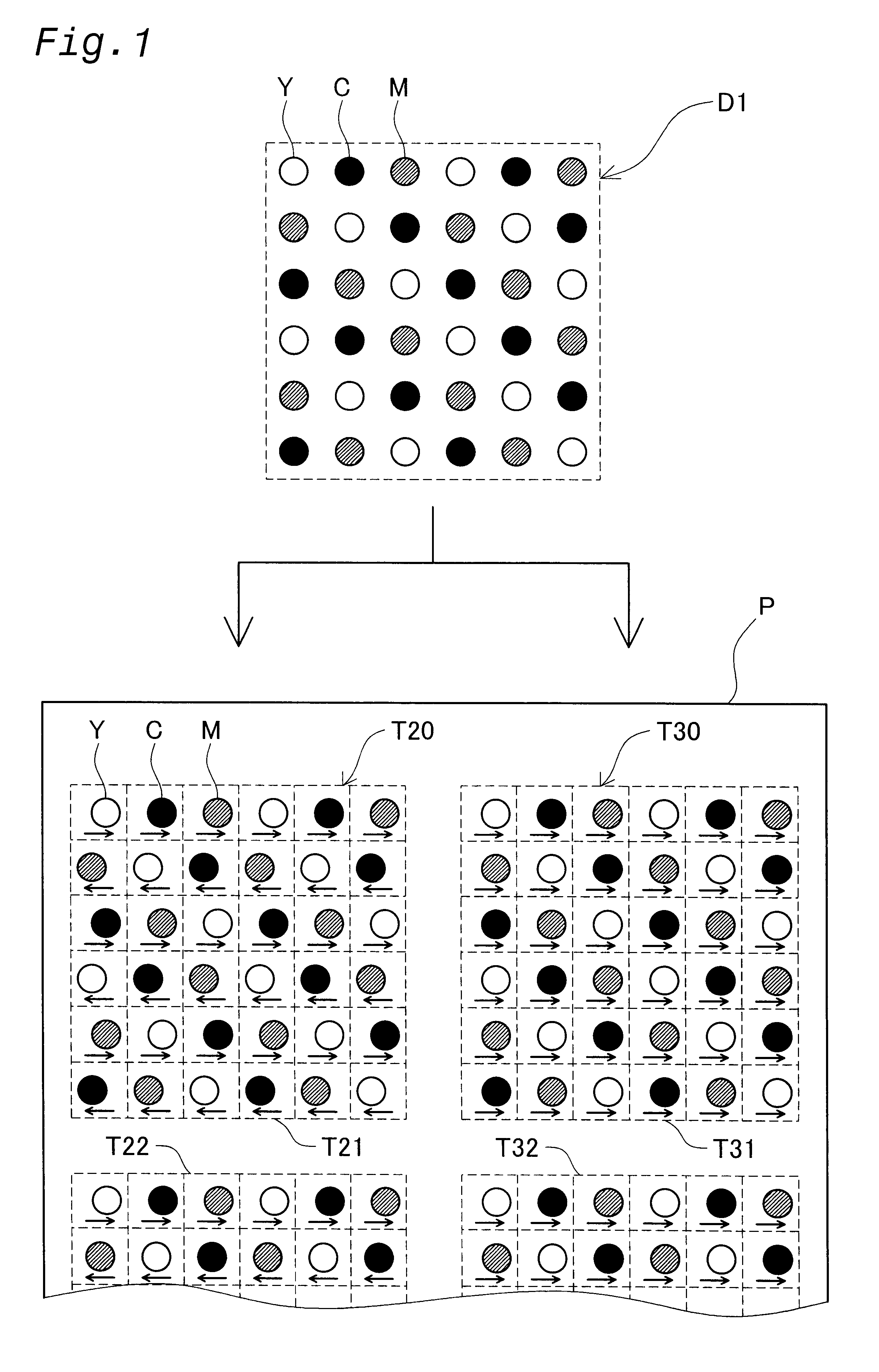
FIG. 7 is a diagram depicting an example of a first misalignment verification pattern T20. In step S1 (see FIG. 6), a first misalignment verification pattern is printed by the printer 20. The first misalignment verification pattern T20 is composed of a plurality of gray patches T21-T25 printed on the forward and reverse passes by light-cyan, light-magenta, and yellow nozzle rows. Each gray patch is designed to reproduce the same color. The gray patches T21-T25 correspond to "the first gray patches...

second working example

E. Second Working Example

According to the first working example, color patches are formed based on the same image data by bidirectional printing and unidirectional printing, the two are compared, bidirectionally printed patterns whose print results have the highest quality are selected, and adjustment values are set. According to a second working example, color patches are formed based on two separate types of image data about each adjustment value, and adjustment values capable of delivering adequate print results are determined for both images. Separate description are given below for bidirectional printing and unidirectional printing.

(1) Bidirectional Printing

FIG. 13 is a plan view depicting a first misalignment verification pattern T20 and a second misalignment verification pattern T40 on printing paper P. The first misalignment verification pattern T20 and second misalignment verification pattern T40 are formed on printing paper P in the same manner as shown in FIG. 8, but the ...

modification 1

F1. Modification 1

FIG. 16 is a plan view depicting a first misalignment verification pattern T20a and a second misalignment verification pattern T30a on printing paper P according to a modification. An adjustment value can be set with consideration for the quality degradation of print results due to errors affecting sub-scanning / feeding if the patches are extended in the direction of sub-scanning, as shown in FIG. 16. The patches T21a-T25a and T31a-T35a (T23a-T25a or T33a-T35a are not shown) should preferably be formed across at least one fourth of the printable area on the printing paper in the direction perpendicular to the direction of main scanning. Forming the patches within this range allows these patches to fully reflect the errors affecting sub-scanning feed when images are printed in the printable area. In this case, a smaller number of patches can be formed on a single sheet of printing paper, but forming the patches on a plurality of sheets of printing paper makes it poss...


PUM


Abstract

Determination of an adjustment value for adjusting the shifting of recording positions is made easier. The adjustment value is one for adjusting the shifting of recording positions in the direction of main scanning when ink drops are ejected and dots formed on a print medium. Patches T21-T25 and patches T31-T35 are printed in order to determine the extent (adjustment value) to which dot formation positions are shifted on a reverse pass during bidirectional printing. Each patch is formed based on the same print data D1 related to yellow (Y), light cyan (LC), and light magenta (LM) dots. Each dot is formed on the forward and reverse passes of main scanning when the patches T21-T25 are formed. The patches are printed by varying the dot recording positions on a reverse pass in small increments. The patches T31-T35 are formed solely on the forward pass of a main scan. The extent (adjustment value) to which the timing for ejecting ink drops with minimal dot formation misalignments is shifted can be determined by selecting from the patches T21-T25 the patch whose print results are the closest to the adjacent patches T31-T35.

Description

The present invention relates to a technique for printing images by forming dots on a print medium during main scanning, and more particularly to a technique for adjusting recording position misalignments in the direction of main scanning and reducing the graininess of images printed in color.BACKGROUND TECHNOLOGYColor printers of the type in which inks of several colors are ejected from a head are currently used on a wide scale as computer output devices. Such color printers include those in which images are printed by ejecting ink drops from nozzles to form dots on a print medium during main scanning.Printing systems can be divided into unidirectional printing systems in which images are printed only during the forward or reverse pass of a main scan, and bidirectional printing systems in which images are printed during both forward and reverse passes. Many of the contemporary color-ink jet printers utilize both unidirectional and bidirectional printing.In a printing operation in w...

Claims


Application Information

Patent Timeline
Patent Type & Authority Patents(United States)
IPC IPC(8): B41J19/14B41J19/00B41J2/21B41J2/01
CPCB41J2/2135B41J19/145
Inventor NUNOKAWA, HIROKAZU
Owner SEIKO EPSON CORP
Why Eureka
Try Eureka