Fixture for an electrical device

a technology for fixing electrical devices and electrical components, applied in the direction of coupling device connections, mechanical devices, fastening means, etc., can solve the problems of inability to precisely position the tenon 11 and stably wedge due, and achieve the effect of quick, easy and stably assembling

Inactive Publication Date: 2004-01-20
CHANG GUO HENG
View PDF8 Cites 48 Cited by
  • Summary
  • Abstract
  • Description
  • Claims
  • Application Information

AI Technical Summary

Benefits of technology

The present invention is relating to a fixture for an electrical device in general, and more particularly to a fixture for rapidly, easily and stably assembling a heat dissipating device and an electrical device.
It is a first object of the present invention to provide a fixture for an electrical device to prevent a spring jumping out from the pin. A ring block is used to limit the spring inside the pin casing. Typically, the ring block is installed against a press portion of a pin to make the spring be compressed.
It is a fourth object of the present invention to provide a fixture for an electrical device that includes a ring block fastened inside the pin casing. By means of the press portion of pin, the ring block is pushed to make the spring be compressed so that the wedge portion of pin is able to wedge the electrical device closely. Therefore, the effect of easily, rapidly and stably wedging the electrical device can be reached.

Problems solved by technology

However, while pushing the tenon 11 by hand, it is unable to make the tenon 11 precisely position and stably wedge due to inclination or shake.

Method used


Image

  • Fixture for an electrical device
  • Fixture for an electrical device
  • Fixture for an electrical device

Examples


Embodiment Construction

Referring to the drawings attached, the present invention will be described by means of the embodiments below.

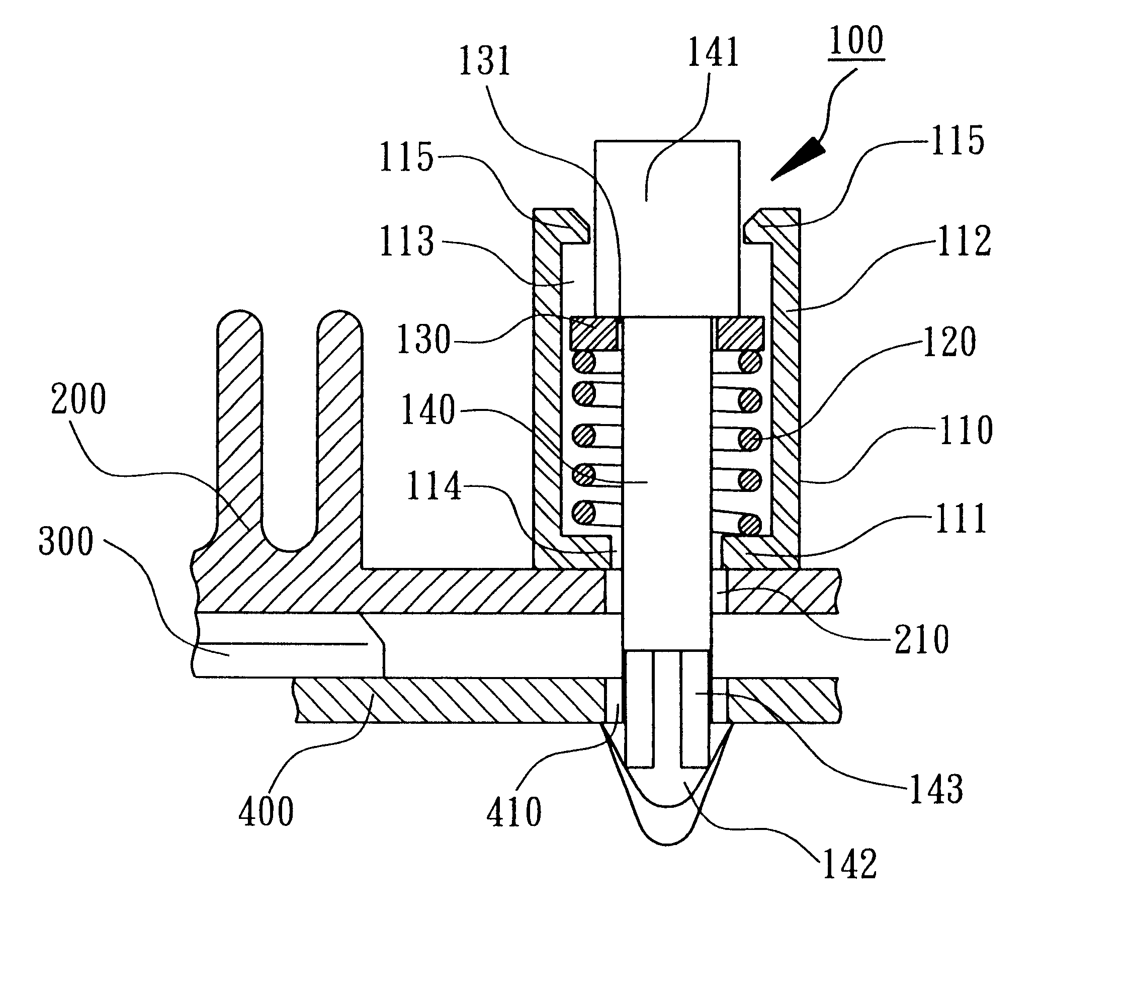
According to an embodiment of the present invention, as shown in FIGS. 5 and 6, a fixture 100 for an electrical device comprises a pin casing 110, a spring 120, a ring block 130 and a pin 140. The pin casing 110 has a trough 113 formed by a bottom 111 and a round-wall 112 in order to place a spring 120, such as helical compression spring or conical compression spring, etc. In this embodiment, the spring 120 is a compression spring for providing the fixture 100 with an elastic anti-push force while pushing to wedge. A through hole 114 is formed on the bottom 111 of pin casing 110 to let the pin 140 passing through. At least a flange 115 is formed on the round-wall 112 of pin casing 110. It is better that a gap 116 is formed at the two sides of the flange 115 respectively to make the flange 115 elastic, so that the round-wall 112 of pin casing 110 is able to outwardly expand f...


PUM


Abstract

A fixture for an electrical device includes a pin casing, a spring, a ring block and a pin. A pin casing has a trough formed from a bottom and a round-wall for containing spring and ring block. The round-wall forms at least a flange to limit ring block inside pin casing. The pin has a press portion and a wedge portion. The wedge portion passes through ring block, spring and pin casing so as to combine those together. The press portion is used for pushing the ring block to compress the spring.

Description

FIELD OF 1THE INVENTIONThe present invention is relating to a fixture for an electrical device in general, and more particularly to a fixture for rapidly, easily and stably assembling a heat dissipating device and an electrical device.It is well known that an electrical device of high power such as CPU will produce much heat in run. In order to prevent damaging an electrical device due to overheat, a heat dissipating device is necessary to be installed for conducting heat from the electrical device. In general a heat dissipating device is a heat sink, a cooling fin or a cooling fan etc, and is directly installed above a heating electrical device by wedging method for conducting or dissipating heat. Therefore, a heat dissipating device needs a stable fixture to be closely installed above an electrical device for a good effect of cooling.As shown in FIG. 1, a fixture 10 for adhering a heat sink 20 on the upper surface of CPU 32 is disclosed in Republic Of China (Taiwan) Patent Publica...

Claims


Application Information

Patent Timeline
Patent Type & Authority Patents(United States)
IPC IPC(8): H01L23/40H01L23/34
CPCH01L23/4093H01L2924/0002H01L2924/00
Inventor CHANG, GUO-HENG
Owner CHANG GUO HENG
Why Eureka
Try Eureka