Spread-spectrum transmission system with filtered multi-carrier modulation

a transmission system and multi-carrier technology, applied in the direction of digital transmission, transmission path multiple use, electrical equipment, etc., can solve the problems of high power jammer, distortion no longer applies, noise re-fractionation of jammer energy,

Inactive Publication Date: 2004-01-20
WSOU INVESTMENTS LLC
View PDF9 Cites 23 Cited by
  • Summary
  • Abstract
  • Description
  • Claims
  • Application Information

AI Technical Summary

Benefits of technology

The invention proposes a solution to the problem of synchronizing subcarriers in a spread spectrum multicarrier transmission system for military applications. It makes it possible to satisfy the discretion constraints that are imposed in military applications.
With differential demodulation, the invention makes it possible to limit the recombination loss caused by the differential demodulation, while still conserving adequate resistance to jamming.
More precisely, the invention provides a spread-spectrum transmission system with multiple carrier modulation in which the signals for transmission over each of the subcarriers are filtered prior to being transmitted over the subcarrier, thereby making it possible on reception to synchronize the various subcarriers in time, and in which each subcarrier carries a plurality of chips that result from spreading a single symbol.
In another embodiment, the various subcarriers are subjected to differential modulation, and each subcarrier carries a number of chips resulting from spreading a single symbol, which number is sufficient to provide resistance to jamming by limiting recombination losses because of the differential modulation.

Problems solved by technology

One of the problems with such spreading techniques is that when the signals are unspread, a fraction of the energy from the jammer is recovered in the form of noise.
This can be a problem with very high power jammers.
Another problem with spreading techniques is the usual assumption that the transmission channel is without distortion no longer applies to the broad band of a spread signal.
However, they do not satisfy the discretion constraint that applies to military systems.
In addition, they are not appropriate to getting rid of any jamming.
In addition to their specific character, those solutions do not operate at low signal-to-noise ratios, which are typical of spectrum spreading.
Such a solution using filtered multiple carriers still implies synchronization which is neither discreet nor robust, as explained above.

Method used


Image

  • Spread-spectrum transmission system with filtered multi-carrier modulation
  • Spread-spectrum transmission system with filtered multi-carrier modulation
  • Spread-spectrum transmission system with filtered multi-carrier modulation

Examples


Embodiment Construction

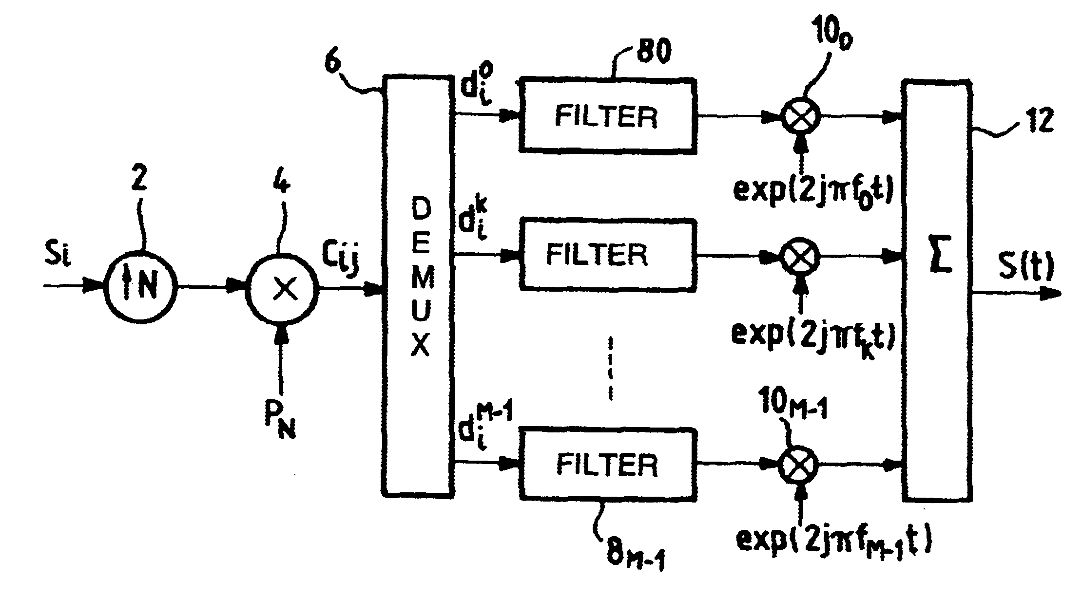
In a spread spectrum transmission system, the invention proposes replacing conventional multicarrier modulation as described with reference to FIG. 3 by filtered multicarrier modulation. A suitable distribution of chips over the various subcarriers then makes it possible to implement receiver synchronization algorithms independently on each of the subcarriers.

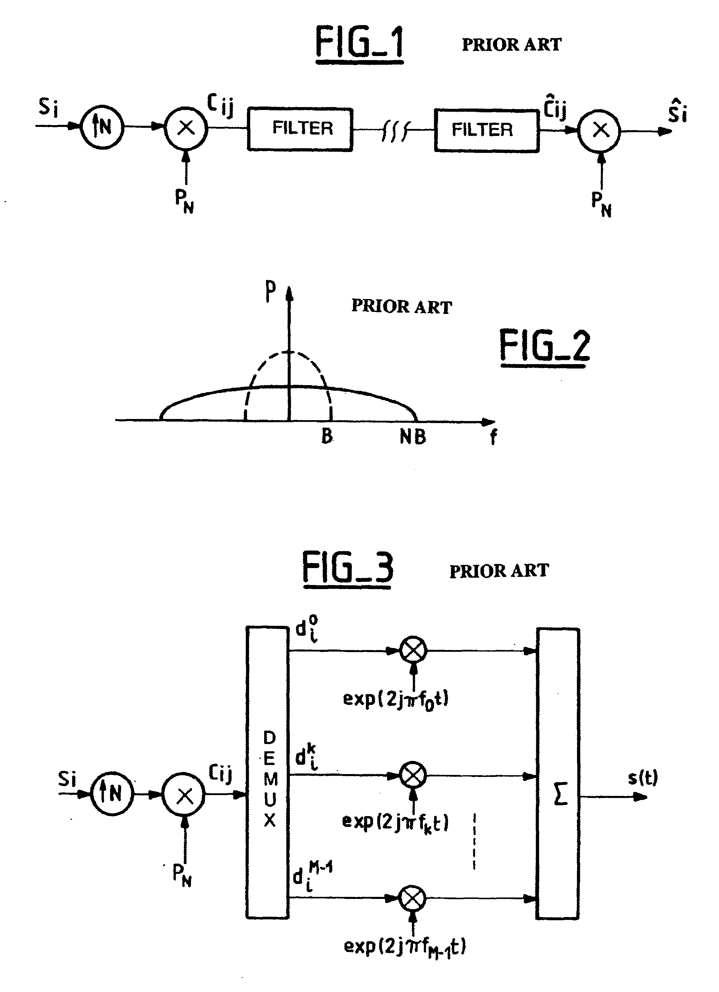
FIG. 5 is a block diagram of a spread spectrum transmission system implementing the invention. As in FIG. 3, this diagram shows input symbols S.sub.i. These symbols are typically real or complex symbols from linear modulation such as M state phase shift keying (M-PSK) or M-state quadratic amplitude modulation (M-QAM). The received symbols S.sub.i are oversampled, as represented by 2 in the figure, and they are then multiplied by a spreading sequence P.sub.N to obtain chips c.sub.i,j as shown at 4 in the figure. The notion P.sub.N does not imply that the spreading sequence is of a length identical to the period of one symbol. It...


PUM


Abstract

The invention provides a spread-spectrum transmission system with multiple carrier modulation in which the signals for transmission over each of the subcarriers are filtered prior to being transmitted over the subcarrier, thereby making it possible on reception to synchronize the various subcarriers in time, and in which each subcarrier carries a plurality of chips that result from spreading a single symbol. With coherent modulation, the number of chips resulting from spreading a single symbol and transmitted over each subcarrier is selected so as to enable the various subcarriers to be put into phase alignment by recombining the chips coming from the same symbol on each subcarrier. With differential modulation, the transmission over each subcarrier of chips resulting from spreading a single symbol provides resistance to jamming by limiting recombination losses because of the differential modulation.

Description

The present invention relates to the field of radio transmission, and more particularly to the field of military tactical transmission. Transmission of such a type needs to be able to satisfy constraints in addition to those of conventional radio transmission; it must be capable of being implemented on numerous types of transmission channel, and in particular on frequency-selective channels. It must be discreet, and it must withstand jamming as well as possible. Finally, it is necessary for transmission of this type to guarantee that the system is robust in terms of ease of acquiring and maintaining synchronization.To withstand jamming, it is known to use spectrum-spreading techniques. These techniques are described, for example, by M. K. Simon et al. in "Spread spectrum communications" published by Computer Sciences Press, 1988. One of the problems with such spreading techniques is that when the signals are unspread, a fraction of the energy from the jammer is recovered in the form...

Claims


Application Information

Patent Timeline
Patent Type & Authority Patents(United States)
IPC IPC(8): H04L5/02H04L27/26
CPCH04L5/023H04L27/2637H04L27/264H04L27/26414H04L27/26538
Inventor LEMOIS, EMMANUELBUDA, FABIENRICHARD, JOEL
Owner WSOU INVESTMENTS LLC
Why Eureka
Try Eureka