Method of displaying high-density dot-matrix bit-mapped image on low-density dot-matrix display and system therefor

a technology of low density dot matrix and high density dot matrix, which is applied in the direction of static indicating devices, instruments, cathode-ray tube indicators, etc., can solve the problems of significant data loss, significant image quality reduction, and image resolution reduction

Inactive Publication Date: 2004-02-10
AVIX
View PDF3 Cites 20 Cited by
  • Summary
  • Abstract
  • Description
  • Claims
  • Application Information

AI Technical Summary

Benefits of technology

It is another object of the present invention to provide a display device having a transparent structure capable of maintaining visibility across its structure.

Problems solved by technology

A significant amount of data is lost and image resolution lowered as a result of this image thinning display control method.
Furthermore, when only this thinning process is applied, an aliasing effect is generated which significantly lowers image quality.
Because of electronic devices for driving the elements installed in the panel structure, the panel structure cannot be transparent.
Obviously, the above conventional display device with a solid panel structure cannot be employed for this use.

Method used


Image

  • Method of displaying high-density dot-matrix bit-mapped image on low-density dot-matrix display and system therefor
  • Method of displaying high-density dot-matrix bit-mapped image on low-density dot-matrix display and system therefor
  • Method of displaying high-density dot-matrix bit-mapped image on low-density dot-matrix display and system therefor

Examples


Embodiment Construction

The discussion concerning the embodiments of the present invention will be prefaced by a discussion of the large-scale low-density dot-matrix display devices to which the present invention can be applied as a control means.

Transparent Display Panel

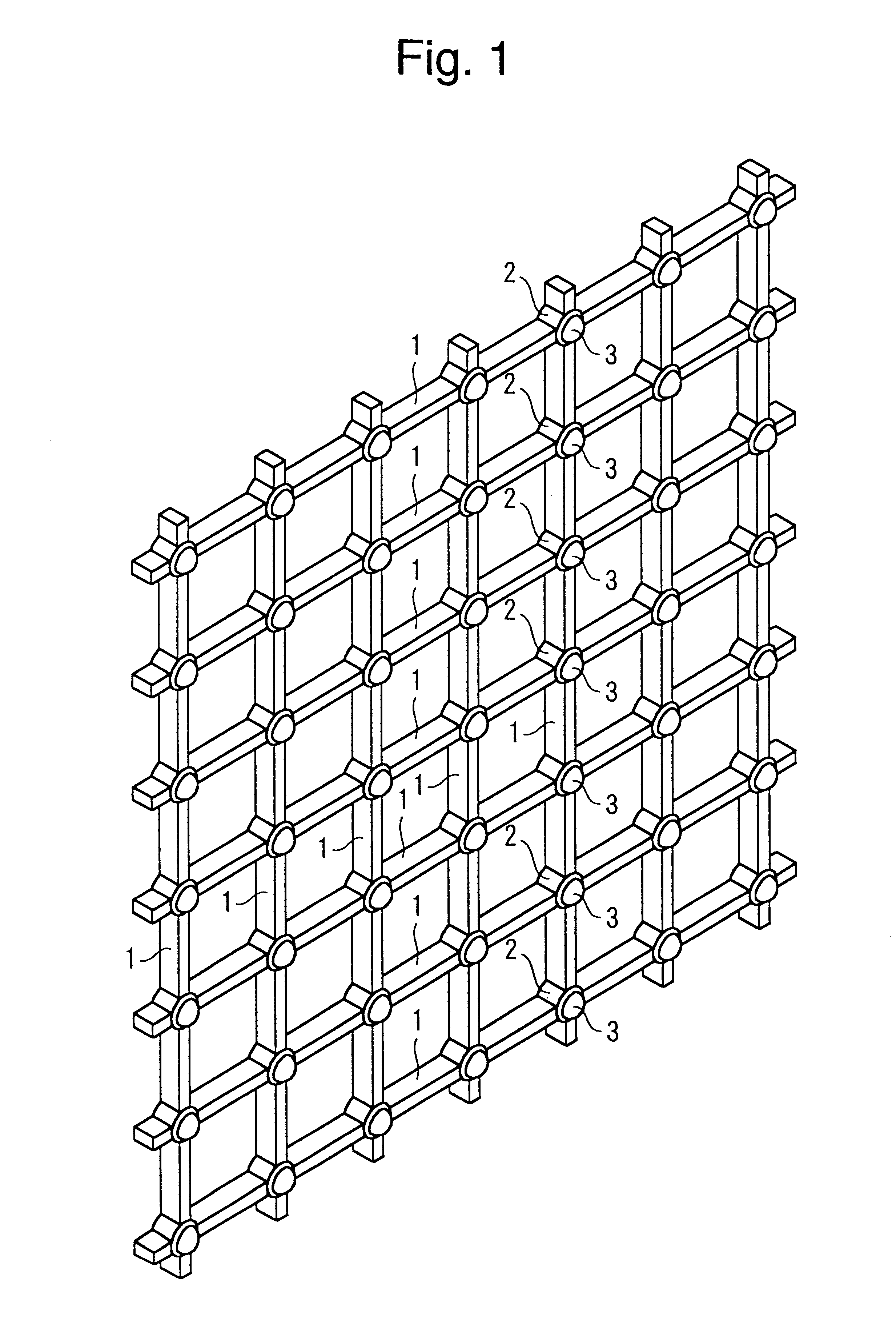
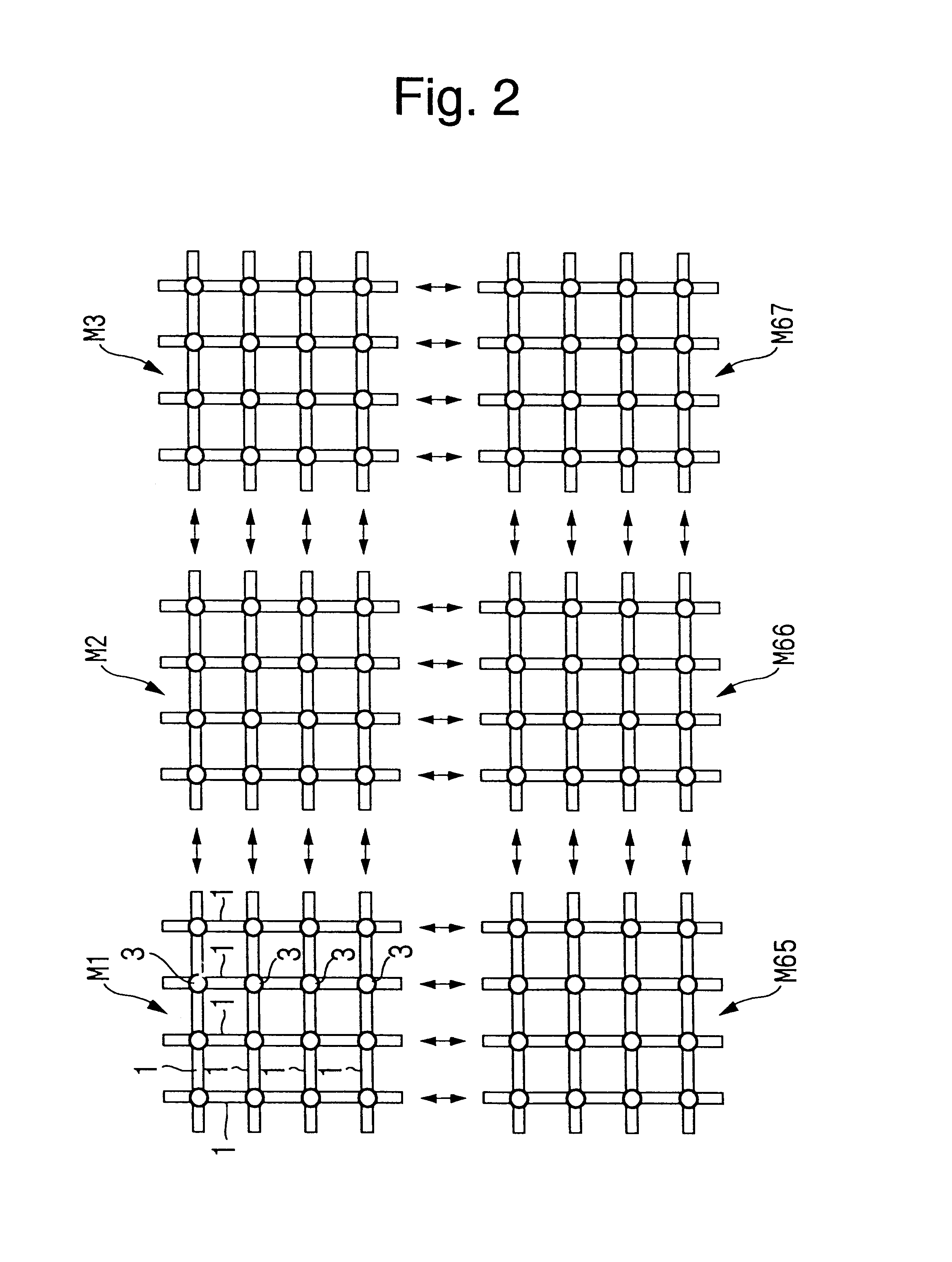
FIG. 1 shows an external view of a transparent type of display panel as one embodiment of the present invention. This display panel comprises vertical and horizontal cross members 1 intersecting at 100 mm intervals to form a non-opaque lattice structure. Each of the cross members 1 is 12 mm in width. Each intersection within the lattice incorporates a 27 mm diameter cylindrical housing 2 which is formed as an integral part of the lattice structure, and high-intensity LED lamps 3 which are installed into each housing 2 and which can incorporate red, green, and blue lamp elements to allow multi-color display. As FIG. 1 shows, the axis of illumination of lamps 3 are perpendicular to the front surface of the display panel.

While FIG. 1 shows se...


PUM


Abstract

A method of and system for displaying high-density bit-mapped dot-matrix imaging data on a large-scale low-density dot-matrix display is disclosed. Bit-mapped image data from each of multiple and adjacently oriented dot image data groups is allocated to drive one dot of the aforesaid display. This is done through a process in which a data selection sequence standard is employed to alternately select and extract image data from each of the aforesaid dot image data groups continually and repetitively at high speed, and in which the extracted image data from each dot image group is applied to drive one dot on the display.

Description

1. Field of the InventionThe present invention relates to a method of using a large screen low-density dot-matrix display device to display high-density bit-mapped dot-matrix image data. Specifically, the present invention relates to a method of obtaining as fine an image as possible through the aforesaid large screen dot-matrix display.2. Description of the Related ArtLarge-scale dot-matrix displays of the type consisting of an array of vertically and horizontally oriented rows of light emitting diodes are frequently used on buildings, in sports stadiums, and at other locations as a means of imparting information visually. These types of displays use large display surfaces which generally offer a similar image resolution to that of conventional television.A typical television receiver offers a level of image resolution equivalent to 480 vertical and 720 horizontal display lines. Bit mapped image data applied to this resolution standard is processed as 480 vertical dots by 720 horiz...

Claims


Application Information

Patent Timeline
Patent Type & Authority Patents(United States)
IPC IPC(8): G09G3/20G09G3/32G09G3/30
CPCG09G3/20G09G3/30G09G3/32G09G2340/0407G09G2340/0414G09G2340/0421G09F9/33G09G5/36
Inventor TOKIMOTO, TOYOTAROOISHI, MASATOSHI
Owner AVIX
Why Eureka
Try Eureka