Transflective liquid crystal display device having reflective and transmissive mode parity

a liquid crystal display and transflective technology, applied in non-linear optics, instruments, optics, etc., can solve the problems of affecting the environment of the reflective lcd device, the battery cannot be used for a long time, and the backlight device's electric power consumption increases

Inactive Publication Date: 2004-02-24
LG DISPLAY CO LTD
View PDF4 Cites 92 Cited by
  • Summary
  • Abstract
  • Description
  • Claims
  • Application Information

AI Technical Summary

Problems solved by technology

For this reason, the transmissive LCD device requires a high, initial brightness, and thus electric power consumption by the backlight device increases.
However, this has a problem that the battery can not be used for a lengthy period of time.
However, the reflective LCD device is affected by its surroundings.
However, since the reflective electrode has the transmitting holes "A", the conventional transflective LCD device has a very low light utilizing efficiency compared to either the reflective LCD device or the transmissive LCD device alone.

Method used


Image

  • Transflective liquid crystal display device having reflective and transmissive mode parity
  • Transflective liquid crystal display device having reflective and transmissive mode parity
  • Transflective liquid crystal display device having reflective and transmissive mode parity

Examples


first embodiment

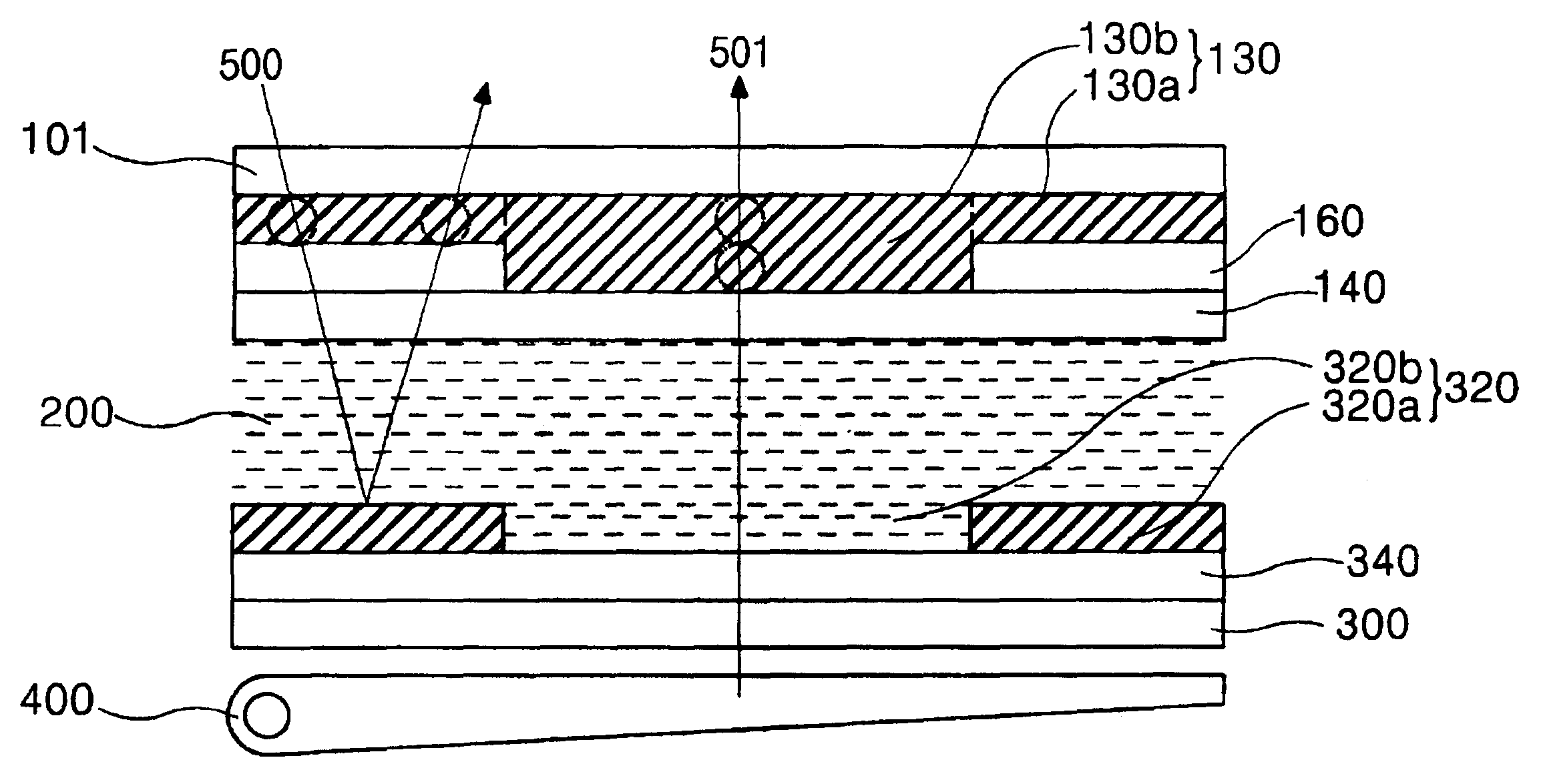
The color filter layer 120 according to the invention can be made of the same resin. The difference between the first and second color filter layers 120a and 120b can be the density of the resin. The first and second color filter layers 120a and 120b are formed in the same plane. If the first and second color filter layers 120a and 120b have the same density as each other and are adopted for the transflective LCD device explained above, the color purity of the first color filter layer 120a would be higher than the second color filter layer 120b. The first color filter layer 120a serves as a color filter in a reflective mode using ambient light 500 and the second color filter layer 120b serves as a color filter in a transmissive mode using light 501 from the backlight device 400. Therefore, in order to provide substantially uniform color purity regardless of the selected mode, it is necessary to enhance color purity of the second color filter layer 120b. To do this, the density of th...

second embodiment

FIG. 7 shows a transflective LCD device according to the invention. The LCD device of FIG. 7 is similar to that shown in FIG. 5, thus explanations of other elements of LCD device are omitted except the different portions.

The differences between the two LCD devices of FIGS. 5 and 7 are that the latter has an additional color filter layer 350 formed on the lower substrate 300 and that the color filter 120 on the liquid crystal material 200 has a uniform density of resin. The thickness of the additional color filter layer 350 is substantially the same as that of the color filter 120.

In this embodiment, to provide uniform color purity regardless of the selected mode, the additional or second color filter layer 350 is positioned between the lower substrate 300 and the reflector 320. Therefore in a transmissive mode, the light 501 from the backlight device 400 passes the second color filter layer 350, and then passes through the transmissive portion 320b of the reflector 320, and finally ...


PUM

PropertyMeasurementUnit
transmittanceaaaaaaaaaa

Abstract

The invention provides a transflective liquid crystal display device which can achieve substantially the same color purity regardless of the selected mode (transmissive or reflective) by controlling the density of a uniformly thick color filter layer or the thickness of a uniformly dense color filter layer, or by having another color filter layer that affects light only in the transmissive mode. The invention emphasizes the thickness of the color filter through which light passes or the density of the color filter through which light passes, in order to achieve substantially uniform color purity.

Description

CROSS REFERENCEThis application claims the benefit of Korean Patent Application Nos. 1999-46946, 1999-56883, and 2000-19715, filed on Oct. 27, 1999, on Dec. 11, 1999, and on Apr. 14, 2000, respectively, under 35 U.S.C. .sctn.119, the entirety of each of which is hereby incorporated by reference.1. Field of the InventionThe present invention relates to a liquid crystal display (LCD) device, and more particularly, to a transflective LCD device.2. Description of Related ArtIn general, liquid crystal displays are divided into transmissive LCD devices and reflective LCD devices according to whether the display uses an internal or external light source.A typical transmissive LCD device includes a liquid crystal panel and a back light device. The liquid crystal panel includes upper and lower substrates with a liquid crystal layer interposed. The upper substrate includes a color filter, and the lower substrate includes thin film transistors (TFTs) as switching elements. An upper polarizer i...

Claims


Application Information

Patent Timeline
Patent Type & Authority Patents(United States)
IPC IPC(8): G02F1/13G02F1/1335
CPCG02F1/133555G02F1/133514
Inventor BAEK, HEUM ILKIM, YONG BEOMHA, KYOUNG SU
Owner LG DISPLAY CO LTD
Why Eureka
Try Eureka