Processes for the production of electro-optic displays, and color filters for use therein

a technology of electrooptic display and process, which is applied in the field of electrooptic display production and filter, can solve the problems of preventing widespread use, inadequate service life of these displays, and gas-based electrophoretic media being susceptible to the same types of problems

Active Publication Date: 2015-12-01
E INK CORPORATION
View PDF250 Cites 113 Cited by
  • Summary
  • Abstract
  • Description
  • Claims
  • Application Information

AI Technical Summary

Benefits of technology

[0038]bringing the second donor sheet adjacent the substrate with the second color filter material facing the substrate, and applying radiation to the second area of the second donor sheet, thereby causing the second area of the second color filter material to become detached from the second donor sheet and deposited on a second area of the substrate.

Problems solved by technology

Nevertheless, problems with the long-term image quality of these displays have prevented their widespread usage.
For example, particles that make up electrophoretic displays tend to settle, resulting in inadequate service-life for these displays.
Such gas-based electrophoretic media appear to be susceptible to the same types of problems due to particle settling as liquid-based electrophoretic media, when the media are used in an orientation which permits such settling, for example in a sign where the medium is disposed in a vertical plane.
Indeed, particle settling appears to be a more serious problem in gas-based electrophoretic media than in liquid-based ones, since the lower viscosity of gaseous suspending fluids as compared with liquid ones allows more rapid settling of the electrophoretic particles.
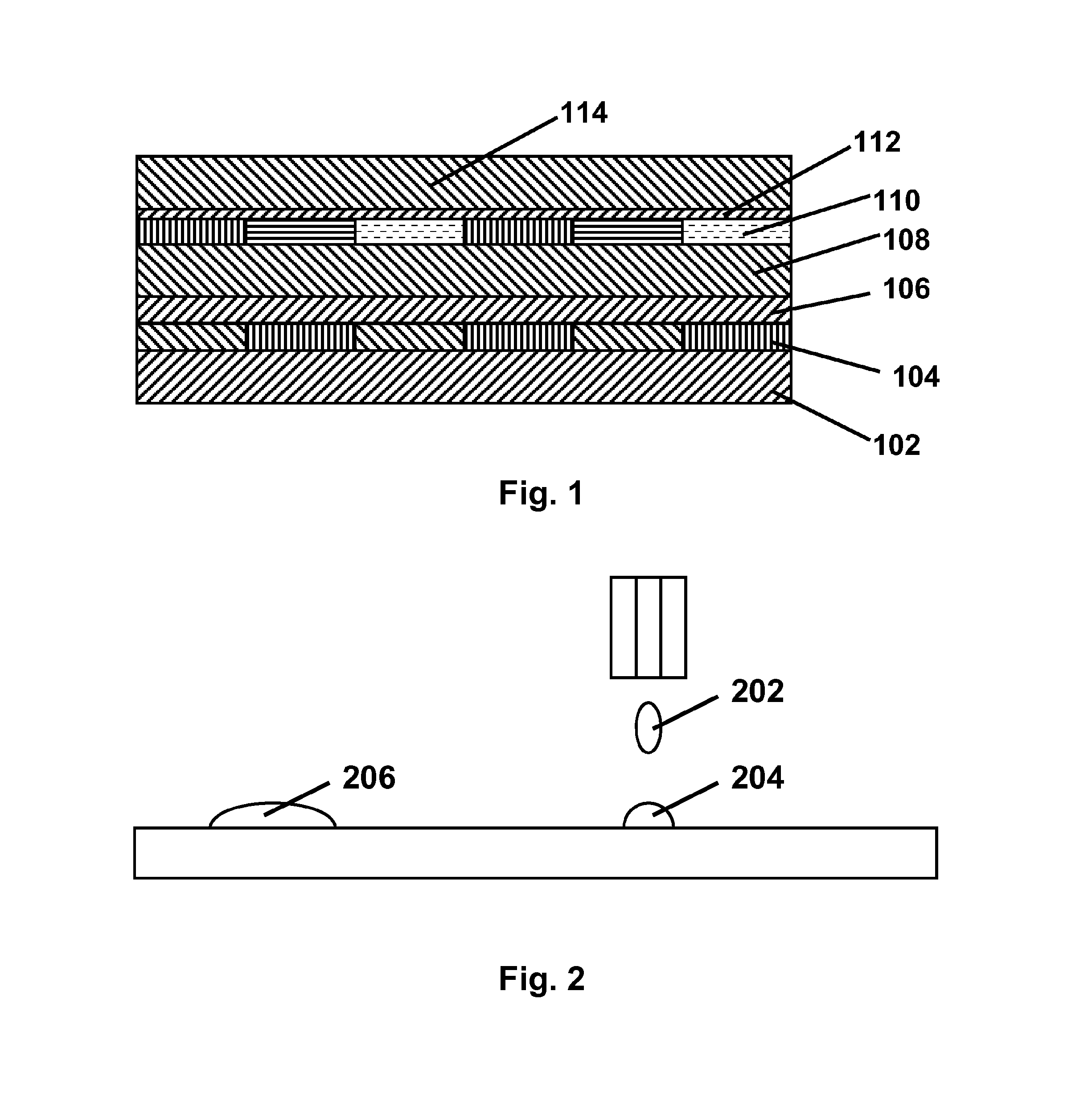
Forming a color filter array such as the array 110 shown in FIG. 1 is not easy, especially in high resolution displays having resolutions of (say) 100 lines per inch (4 lines per mm) or more, since if such arrays are formed using red, green and blue lines, the individual colored lines will be only about 1 / 300 inch (about 80 μm) wide.
Forming such fine colored lines using conventional printing techniques is difficult, especially since many printing techniques allow the printed material to spread laterally after printing.
In a color filter array, it is highly desirable that the colored lines touch but do not overlap, since any gaps between adjacent lines will produce in effect an unanticipated white area in the color filter array and will result in a (typically non-uniform) decrease in color saturation, whereas any overlap will cause color distortion in the final display.
A further difficulty in color filter arrays is aligning such arrays with the sub-pixel electrodes of the display's backplane.
Especially in high resolution displays, maintaining the necessary alignment between the color filter array and the sub-pixel electrodes is difficult, and this problem becomes especially acute in thin, flexible electro-optic displays.

Method used


Image

  • Processes for the production of electro-optic displays, and color filters for use therein
  • Processes for the production of electro-optic displays, and color filters for use therein
  • Processes for the production of electro-optic displays, and color filters for use therein

Examples


Embodiment Construction

[0058]As already mentioned, the present invention provides three different processes for depositing multiple types of color filter materials on a substrate. These three processes will primarily be described separately below, but first consideration will be given to certain issues common to all of the processes.

[0059]The processes of the invention are of course restricted to color filter materials which can survive the process without loss of their color or color-developing ability, and (in some cases) which can be prepared in the necessary flowable or liquid forms. Similarly, a color filter material which cannot be formed into a substantially solid layer, which can be ruptured as required to enable portions of the layer to be transferred from a donor sheet to a substrate, is not suitable for use in the donor sheet transfer process of the present invention. Displays of the present invention may include electro-optic media of any of the types discussed above. For example, the electro-...


PUM

PropertyMeasurementUnit
wavelengthaaaaaaaaaa
viscosityaaaaaaaaaa
areaaaaaaaaaaa

Abstract

Processes are provided for depositing multiple color filter materials on a substrate to form color filters. In a first process, the surface characteristic of a substrate is modified by radiation so that a flowable form of a first color filter material will be deposited on a first area, and converted to a non-flowable form. A second color filter material can then be deposited on a second area of the substrate. In a second process, first and second color filter materials are deposited on separate donor sheets and transferred by radiation to separate areas of the substrate. A third process uses flexographic printing to transfer the first and second color filter materials to the substrate.

Description

REFERENCE TO RELATED APPLICATIONS[0001]This application claims benefit of application Ser. No. 60 / 946,863, filed Jun. 28,2007.[0002]This application is also related to:[0003](a) U.S. Patent Publication No. 2004 / 0190114 (now U.S. Pat. No. 7,667,684); and[0004](b) U.S. Pat. No. 7,339,715.[0005]The entire contents of this application, publication and patent, and of all other U.S. patents and published and applications mentioned below, are herein incorporated by reference.BACKGROUND OF INVENTION[0006]This invention relates to processes for the production of electro-optic displays and for filters for use in such displays.[0007]The term “electro-optic”, as applied to a material or a display, is used herein in its conventional meaning in the imaging art to refer to a material having first and second display states differing in at least one optical property, the material being changed from its first to its second display state by application of an electric field to the material. Although th...

Claims


Application Information

Patent Timeline
Patent Type & Authority Patents(United States)
IPC IPC(8): G02B5/20B32B37/24G03F7/00B32B37/00G02F1/167B32B38/00G02F1/1677
CPCB32B37/24G02B5/201G03F7/0007B32B37/0053B32B37/025Y10T428/24802B32B2038/0076B32B2310/0843B32B2457/202G02F1/167B32B2037/243G02F1/1677G02F1/133519B05D3/06G02F1/133516G02F1/157
Inventor DANNER, GUY M.
Owner E INK CORPORATION
Why Eureka
Try Eureka