Antenna array calibration

a technology for antenna arrays and antenna arrays, applied in wave based measurement systems, instruments, electrical equipment, etc., can solve the problems of complex transceiver hardware in a full duplex communication system, and the inability to use large antenna arrays, so as to achieve easy replication and increase spectral efficiency

Active Publication Date: 2010-05-11
NAT UNIV OF IRELAND MAYNOOTH
View PDF16 Cites 17 Cited by
  • Summary
  • Abstract
  • Description
  • Claims
  • Application Information

AI Technical Summary

Benefits of technology

[0015]The present invention has the advantage that it avoids the complexity of the prior art by employing low-cost, hard-wired and easily replicated reference transceivers.
[0016]Furthermore, the combination of multi-reference calibration and the exploitation of wired calibration result in increased spectral efficiency.

Problems solved by technology

The difficulty in employing antenna arrays is that, in order avoid beamforming errors, the individual antennae each require stimulation at a correct radio frequency (RF) amplitude and phase.
The drawback associated with wired calibration schemes is that they are impractical for use with large antenna arrays because of the need to connect all of the elements of the array back to a reference transceiver.
While practical in simplex systems, for example, radar systems, such a scheme has the disadvantage of requiring complex transceiver hardware in a full duplex communication system.

Method used


Image

  • Antenna array calibration
  • Antenna array calibration
  • Antenna array calibration

Examples


Embodiment Construction

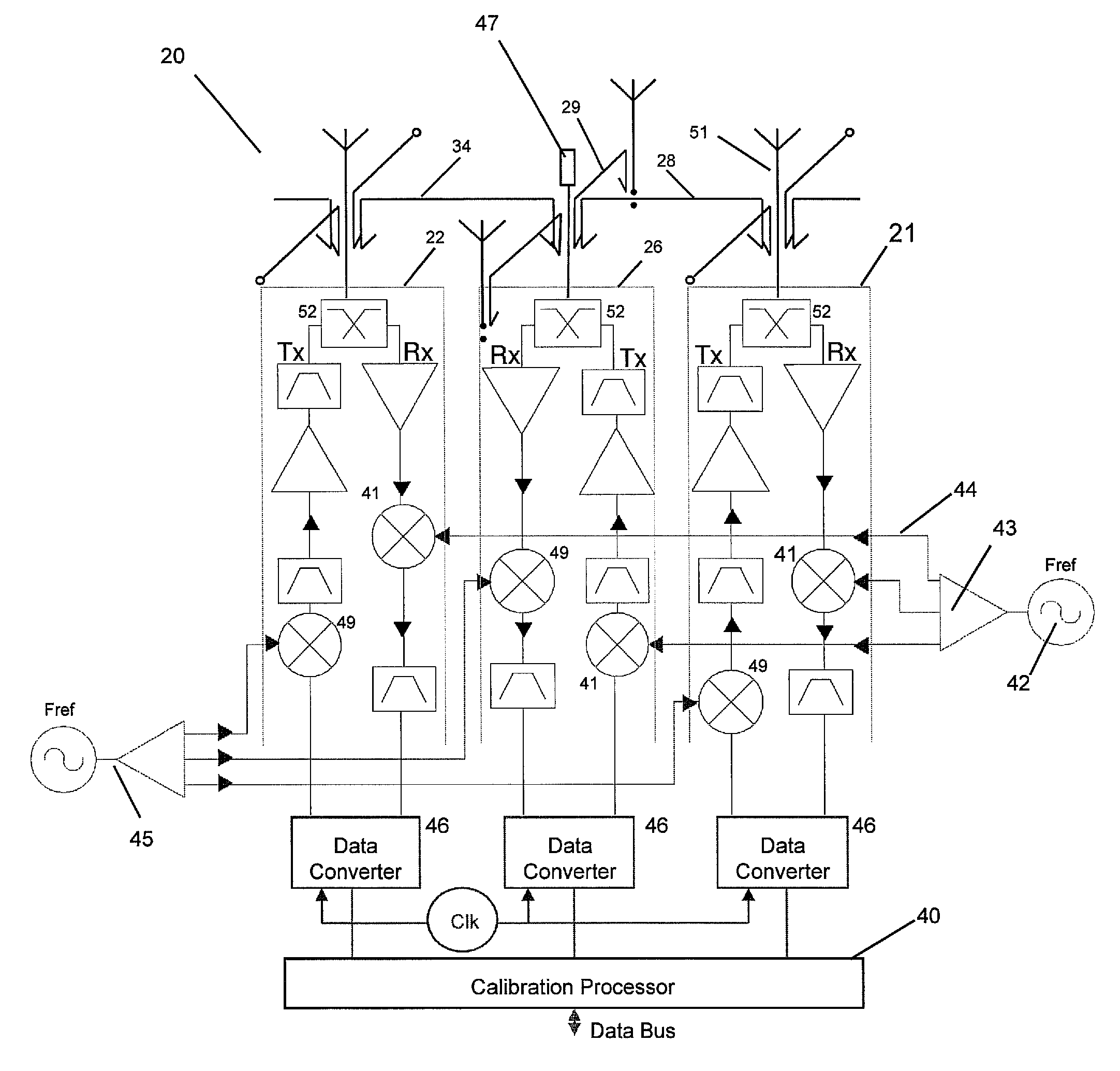
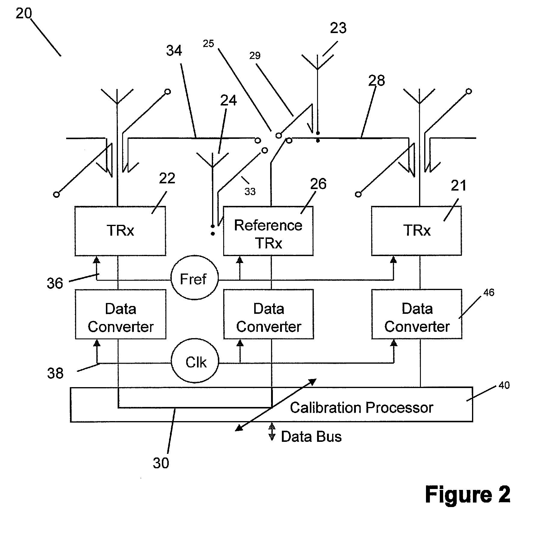
[0028]Referring now to FIG. 2, there is depicted a portion 20 of an antenna array according to an embodiment of the present invention.

[0029]This portion 20 comprises first and second transceivers and their antenna 21 and 22 and the antennae for third and fourth transceivers 23 and 24, respectively, as well as a dedicated non-radiative reference transceiver 26.

[0030]In the preferred embodiment, a coupled electromagnetic calibration path 28 is provided between the first transceiver 21 and the reference transceiver 26. Similarly, a coupled electromagnetic calibration path 34 is provided between the second transceiver 22 and the reference transceiver 26.

[0031]In addition, a feedback path 30, is provided between the second, third and fourth transceivers 22, 23 and 24 and the reference transceiver 26. To ensure all of the elements of the array are frequency coherent, a single signal generator signal (Fref) is distributed through a network 36 between all of the array transceivers. This sig...


PUM


Abstract

An antenna array comprises a surface comprising a replicated pattern of conductive tracks, the tracks defining a plurality of ports. A plurality of antennae are located at ports distributed about the surface. A plurality of radiative transceivers are electrically connected to a respective antenna. A plurality of reference transceivers are electrically connected to a non-radiative impedance located at a respective port so that each reference transceiver is surrounded by a group of antennae and electrically coupled to the group of antennae by the tracks. At least one antenna from at least one group of antennae belongs to one other group of antennae. Calibration circuitry includes a controller associated with each reference transceiver, each controller being arranged to transmit a calibration signal through an associated reference transceiver and to receive and store a received calibration signal from a selected transceiver for the group of antennae coupled to the reference transceiver. Each controller is further arranged to receive and store a calibration signal from the selected transceiver for the group of antennae coupled to the reference transceiver. The calibration circuitry further includes for each other transceiver for the group of antenna, circuitry for adjusting the phase and amplitude of signals transmitted and received by the radiative transceivers relative to the stored calibration signals for the selected radiative transceiver.

Description

[0001]This application is a 35 U.S.C. 371 national phase application of PCT / EP2007 / 004432 filed May 18, 2007, which claims the benefit of Irish application S2006 / 0482 filed Jun. 27, 2006, the disclosures of which are incorporated herein by reference in their entireties.FIELD OF THE INVENTION[0002]The present invention relates to antenna arrays and in particular a method for calibrating an antenna array.BACKGROUND OF THE INVENTION[0003]An antenna array comprises a plurality of elements, here, each including an antenna and an associated transceiver. The antennae are arranged in a manner and the transceivers driven such that radiation emanating from the array may be steered electrically. This is known as beamforming.[0004]The difficulty in employing antenna arrays is that, in order avoid beamforming errors, the individual antennae each require stimulation at a correct radio frequency (RF) amplitude and phase. This requires an electrical path between transceivers and antenna elements to...

Claims


Application Information

Patent Timeline
Patent Type & Authority Patents(United States)
IPC IPC(8): G01S7/40
CPCH01Q3/267H04B17/20H04B17/10
Inventor COOPER, TIMOTHY S.BALDWIN, GERARDFARRELL, RONAN
Owner NAT UNIV OF IRELAND MAYNOOTH
Why Eureka
Try Eureka