Chip removing machining of a workpiece while applying high pressure cooling liquid

a technology of cooling liquid and workpiece, applied in the direction of turning machine accessories, shaping cutters, manufacturing tools, etc., can solve the problems of destroying the components being machined, and affecting the operation of the machin

Inactive Publication Date: 2004-03-16
SANDVIK INTELLECTUAL PROPERTY AB
View PDF11 Cites 97 Cited by
  • Summary
  • Abstract
  • Description
  • Claims
  • Application Information

AI Technical Summary

Problems solved by technology

For this reason, the chips leave the cutting edge in the form of long, tangled chips, which may cause interruptions in the machining process as well as also destroy the components being machined.
An additional disadvantage is the subsequent chip handling, especially disposal of unwieldy chip tangles, which may mean a risk of injury for the operator.
However, in this connection, it should be pointed out that the jet characteristics which provide an optimum chip control do not always ensure an optimum temperature control / cooling of the chip removing machining.

Method used


Image

  • Chip removing machining of a workpiece while applying high pressure cooling liquid
  • Chip removing machining of a workpiece while applying high pressure cooling liquid
  • Chip removing machining of a workpiece while applying high pressure cooling liquid

Examples


Embodiment Construction

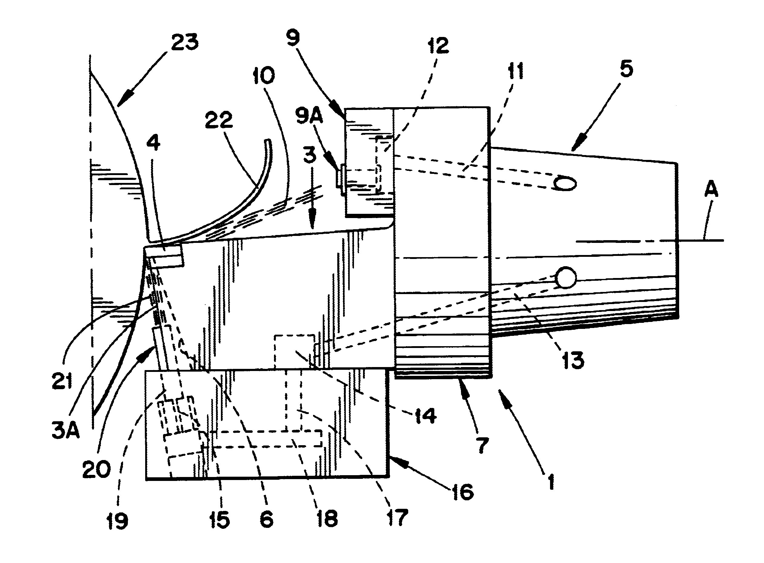
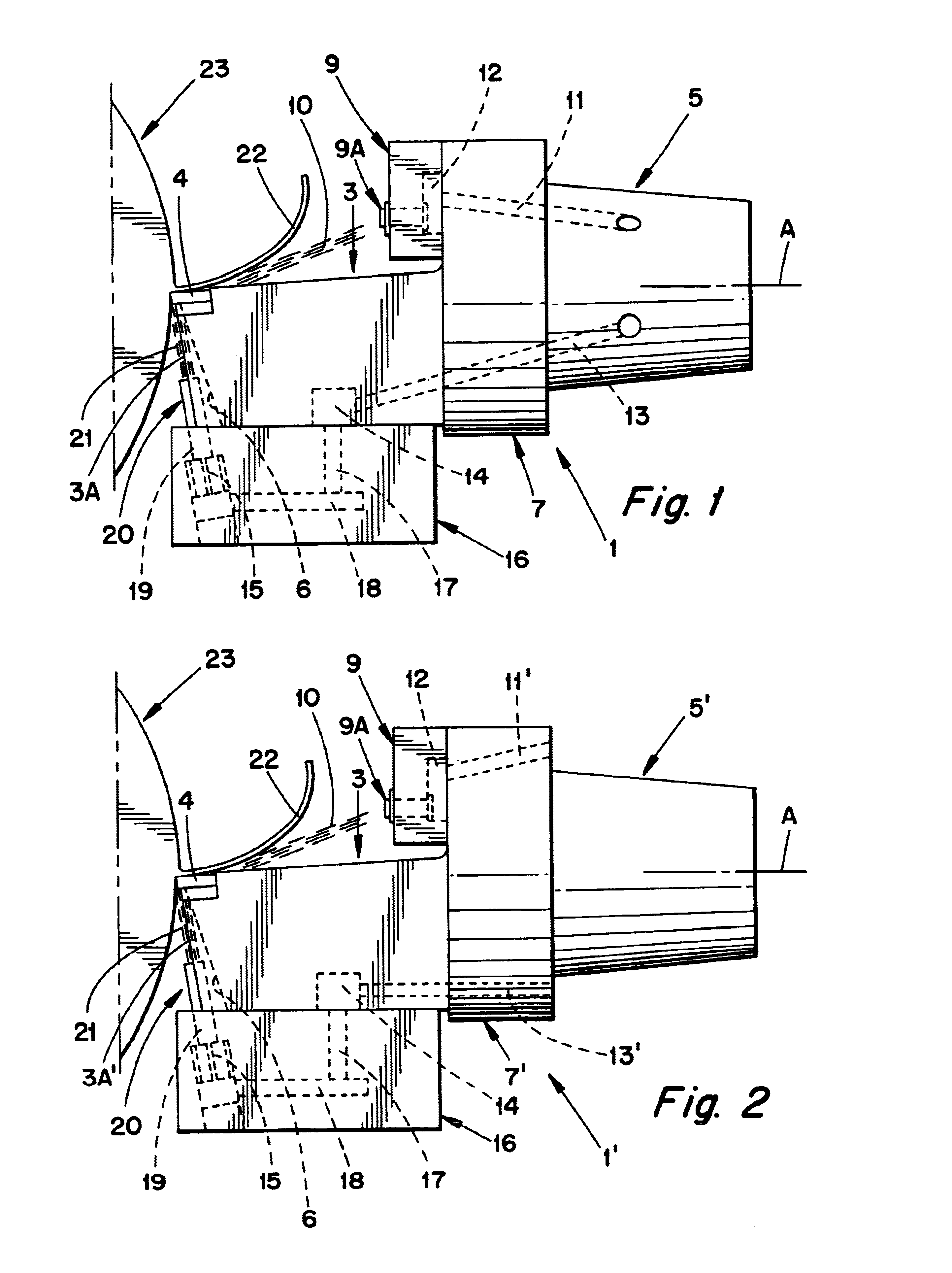
The cutting tool 1 illustrated in FIG. 1 for chip removing machining comprises a front part 3, which has a cutting seat for a replaceable indexable insert 4. A rear part 5 of the cutting tool 1 is formed as a male part, which is intended to be received in a holder (not shown) of a machine tool. The rear part 5 may be of any suitable shape. For instance, in FIG. 1 the rear part 5 has the shape of a truncated cone. Between the front part 3 and the rear part 5, a flange 7 is arranged, said flange forming a stop face against the holder and can be formed with members for effecting automatic tool exchange.

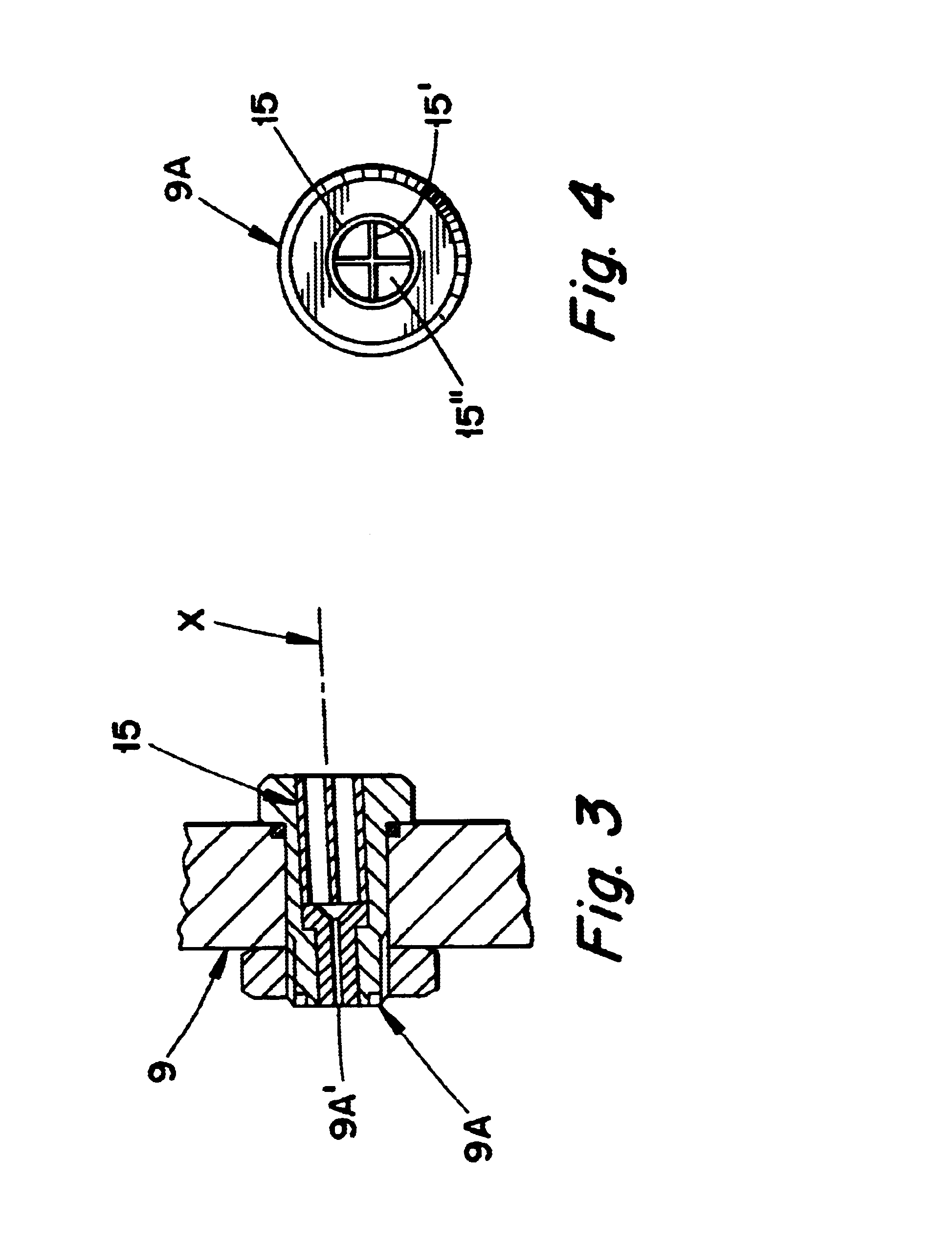
As is seen in FIG. 1, the cutting tool 1 is provided with a plate-shaped nozzle carrier 9, which is applied on the side of the flange 7 facing the front part 3. In the nozzle carrier 9, one or more first or upper nozzles 9A (only one shown) is mounted, whereby said first nozzle sprays a first jet of liquid 10, with high pressure, obliquely from above towards the replaceable indexable ins...


PUM

PropertyMeasurementUnit
pressureaaaaaaaaaa
pressureaaaaaaaaaa
areaaaaaaaaaaa

Abstract

The chip removing machining of a workpiece is performed by a cutting tool which includes a cutting insert. In order to cool the cutting insert, one or more over-cooling nozzles is arranged for directing a jet of cooling liquid downwardly toward a contact area between the workpiece and a chip surface of the cutting insert. A sub-cooling nozzle is arranged for directing a jet of cooling liquid upwardly toward a contact area between the workpiece and a flank surface of the cutting insert. A jet of cooling liquid can be emitted from only the over-cooling nozzle, or from only the sub-cooling nozzle, or from both of those nozzles simultaneously.

Description

This application claims priority under 35 U.S.C. .sctn..sctn.119 and / or 365 to patent application Ser. No. 0100652-7 filed in Sweden on Feb. 27, 2001, the entire content of which is hereby incorporated by reference.The present invention relates to a method for chip removing machining, wherein a so-called high pressure cooling is applied. At least one jet of cooling liquid under high pressure is directed towards the contact area between a cutting edge of a cutting insert for chip removing machining and the workpiece that the cutting insert machines. The invention also relates to a cutting tool for chip removing machining.PRIOR ARTA cutting tool where one or more jets of cooling liquid under high pressure is sprayed in the area between the chip and the chip surface of the cutting insert is previously known from, for instance, Swedish Patent No. 513 480. This type of cooling / chip control henceforth will be denominated as "over-cooling," because the jet is directed downwardly toward the...

Claims


Application Information

Patent Timeline
Patent Type & Authority Patents(United States)
IPC IPC(8): B23Q11/10B23B27/00B23B27/10B23Q11/00
CPCB23B27/10B23Q11/10Y10T82/10Y10T407/14B23Q11/1084
Inventor LAGERBERG, STIG
Owner SANDVIK INTELLECTUAL PROPERTY AB
Why Eureka
Try Eureka