Implantable prosthesis having at least two sections which can be displaced in relation to one another, and the use of displaceable sections

Inactive Publication Date: 2004-04-13
SYNTHES USA
View PDF16 Cites 98 Cited by
  • Summary
  • Abstract
  • Description
  • Claims
  • Application Information

AI Technical Summary

Problems solved by technology

Displacement of the joint or humerus head is effected stepwise and cannot therefore be adapted to the factors involved in all situations.
In addition the structur

Method used


Image

  • Implantable prosthesis having at least two sections which can be displaced in relation to one another, and the use of displaceable sections
  • Implantable prosthesis having at least two sections which can be displaced in relation to one another, and the use of displaceable sections
  • Implantable prosthesis having at least two sections which can be displaced in relation to one another, and the use of displaceable sections

Examples


Embodiment Construction

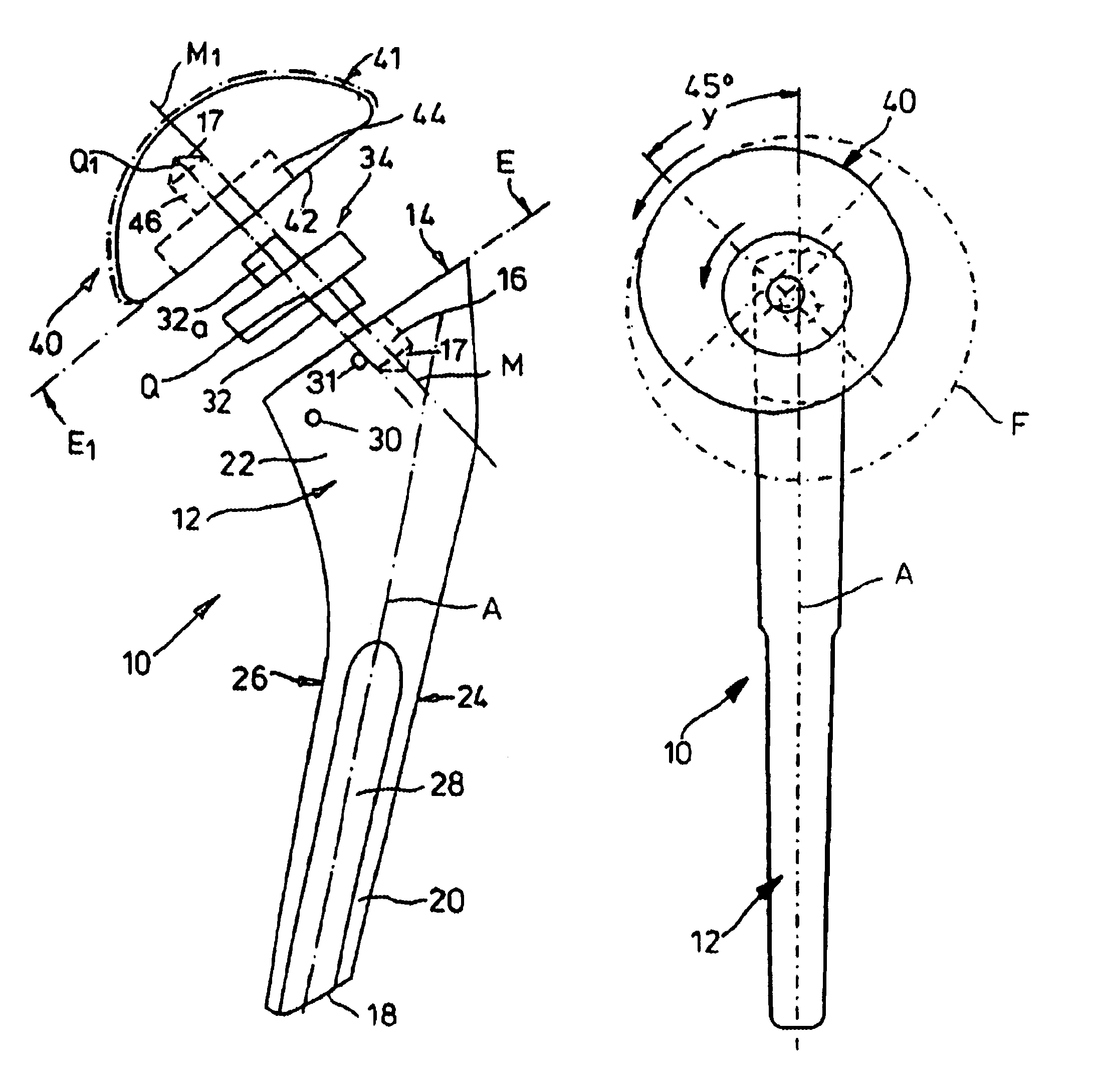
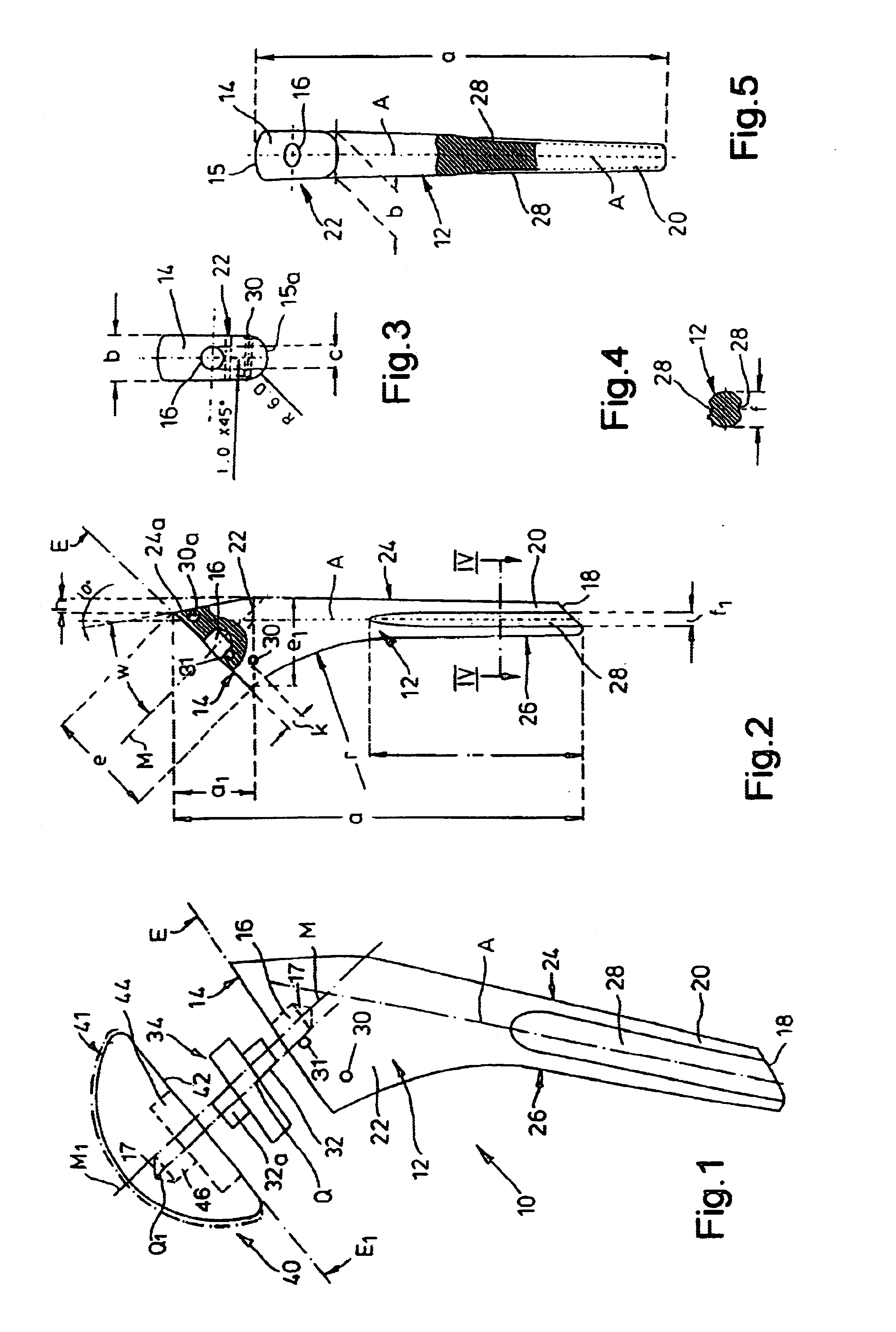
A prosthesis 10 for a human shoulder joint (not shown) comprises a shaft 12 with an end face 14 whose center axis M is inclined relative to the longitudinal axis A of the shaft 12 at an angle w of 45.degree.. The greatest length a of the shaft 12 measures 125 mm, the width b of the end face 14 measures about 14 mm and the length e thereof measures about 23 mm. The projection length e', which can be seen in FIG. 2, of the end face 14 into a plane which crosses the longitudinal axis A at a right angle is then 27.3 mm.

The center axis M of the end face 14 determines therein the position of a blind hole 16 of a diameter d of about 7 mm with a conical end 17. Opposite the free shaft end--which terminates at a suitable base surface 18--of a width f of 11 mm the head region 22 of the shaft 14 is enlarged to the length e or e.sub.1. The upper, slightly rounded narrow edge 15 of the end face 14 is displaced with respect to a condition of alignment with the side 24 of its shaft by virtue of an...


PUM


Abstract

An implantable prosthesis having at least two portions which are displaceable relative to each other, in particular a prosthesis for the upper end of a human upper arm comprising a shaft which can be inserted into a bone passage and a dome-shaped joint head which is to be associated with the adjacent joint head and which can be connected to an end face of the shaft in an eccentric position or a neutral position relative to the center axis thereof by means of an intermediate disk which has a circular periphery and which comprises both in relation to the joint head and in relation to the shaft a respective insert pin or the like peg-shaped portion formed thereon which can be inserted into a bore, wherein the mutually displaceable portions of the prosthesis are arranged steplessly displaceably relative to each other at at least one displacement plane which is determined by the surface of a portion about axes which are determined by the insert pins of the intermediate disk.

Description

(1). Field of the InventionThe invention comprises an implantable prosthesis having at least two portions which are displaceable relative to each other, in particular a prosthesis for the upper end of a human upper arm comprising a shaft which can be inserted into the humerus passage thereof and a dome-shaped joint head which is to be associated with the joint socket adjacent to the upper arm and which can be connected to an end face of the shaft in an eccentric position relative to the center axis thereof by means of an intermediate disk which has a circular periphery and which comprises both in relation to the joint head and in relation to the shaft a respective insert pin or the like peg-shaped portion formed thereon which can be inserted into a bore. The invention also concerns the use of displaceable portions and an intermediate disk on a displacement plane.(2). Description of the Related ArtA joint prosthesis of that kind is to be found in EP 0 549 480 A1. A central insert pin...

Claims


Application Information

Patent Timeline
IPC IPC(8): A61F2/30A61F2/40A61F2/32A61F2/00A61F2/44A61F2/38A61F2/36A61F2/34A61F2/42
CPCA61F2/4014A61F2/34A61F2/36A61F2/38A61F2/3804A61F2/40A61F2/4059A61F2/4202A61F2/4261A61F2/442A61F2002/30112A61F2002/30153A61F2002/30329A61F2002/30341A61F2002/30357A61F2002/30507A61F2002/30542A61F2002/30574A61F2002/30604A61F2002/30617A61F2002/30714A61F2002/30785A61F2002/30795A61F2002/30813A61F2002/30827A61F2002/3656A61F2002/4018A61F2002/4029A61F2002/4037A61F2002/4044A61F2002/4062A61F2002/4077A61F2220/0025A61F2220/0033A61F2230/0004A61F2230/0019A61F2250/0089A61F2250/0097A61F2002/30339A61F2002/3054A61F2002/3071
Inventor KROPF, PHILIPP
Owner SYNTHES USA
Why Eureka
Try Eureka