Torque wrench with a scale

a technology of torque wrench and scale, which is applied in the field of torque wrench, can solve the problems of scale easily being worn off and the scale losing its indicating function after a long time of us

Inactive Publication Date: 2004-04-20
HSIEH CHIH CHING
View PDF9 Cites 41 Cited by
  • Summary
  • Abstract
  • Description
  • Claims
  • Application Information

AI Technical Summary

Benefits of technology

The handle (21) is mounted around the second end of the shank (10) and is made of a flexible material such as a rubber material, silicone or the like. A mouth (210) is formed on one end of the handle (21) and surrounds the stepped protrusion (231) of the adjusting knob (23). A notch (211) is defined in the periphery of the mouth (210) on the handle (21) and corresponds to the scale (232) on the stepped protrusion (231). An extension (212) extends from the bottom of the notch (211) in a length shorter than the depth of the notch (211), such that a window (not numbered) is defined in the second end of the handle (21) for the scale (232) on the stepped protrusion (231) to be shown from the window. An index line (213) is formed on the top of the extension (212) and corresponds to the scale (232) on the stepped protrusion (231). Accordingly, the scale (232) can be easily read through the window with the index line (213). Because the scale (232) is formed on the stepped protrusion (231) received in the mouth (210) on the handle (21), the fingers of the user will not touch the scale (232) when the user rotates the adjusting knob (23). Therefore, the scale (232) will not be worn off, and the useful life of the torque wrench is prolonged.

Problems solved by technology

However, as the scale of the conventional torque wrench is exposed on the outer periphery of the adjusting knob, the scale is easily worn off when the user rotates the adjusting knob.
The scale will lose its indicating function after a long time of use.

Method used


Image

  • Torque wrench with a scale
  • Torque wrench with a scale
  • Torque wrench with a scale

Examples


Embodiment Construction

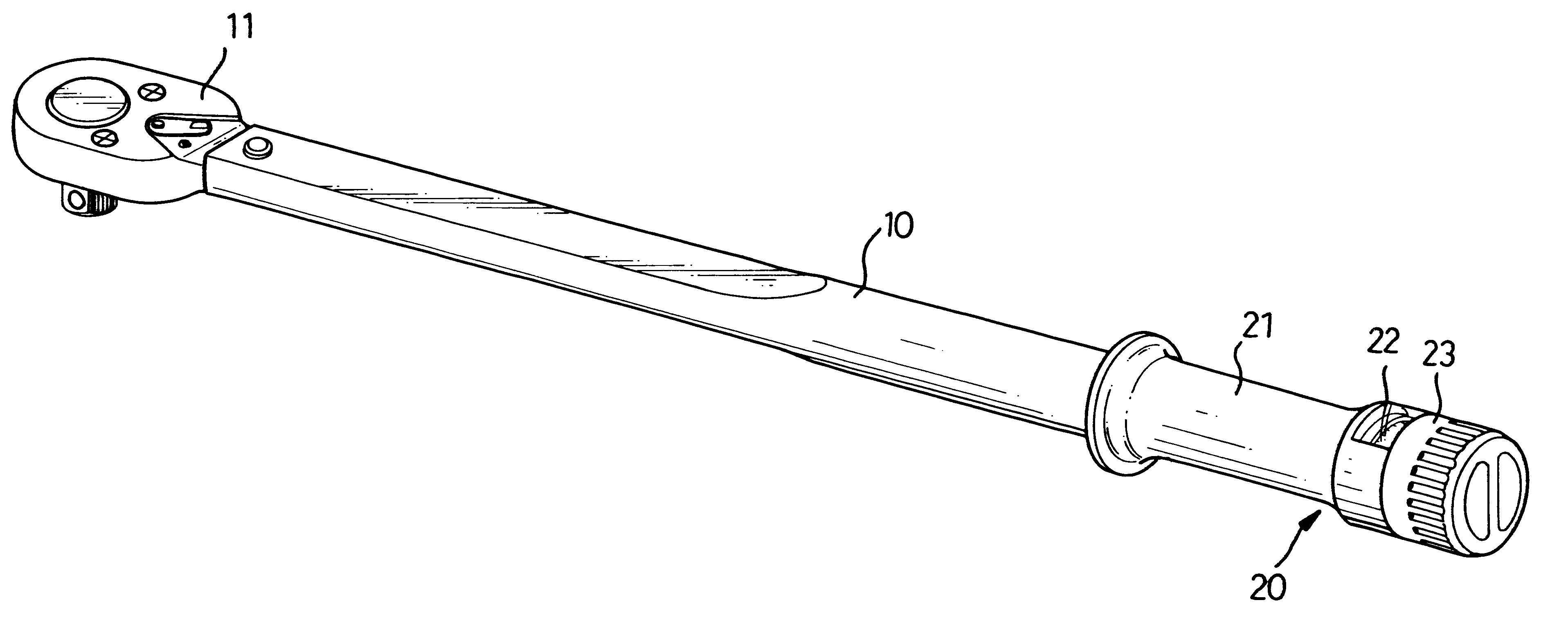
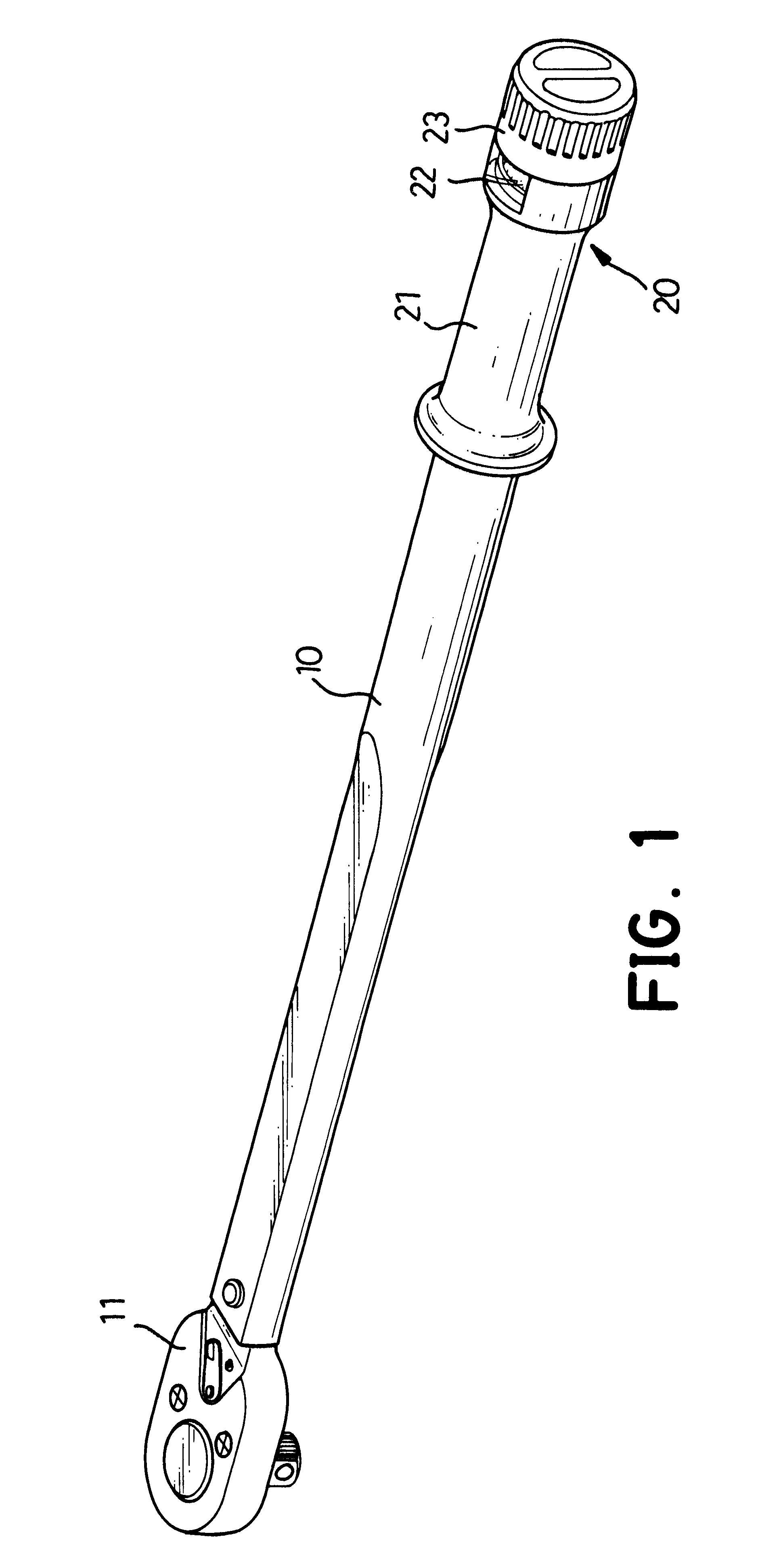
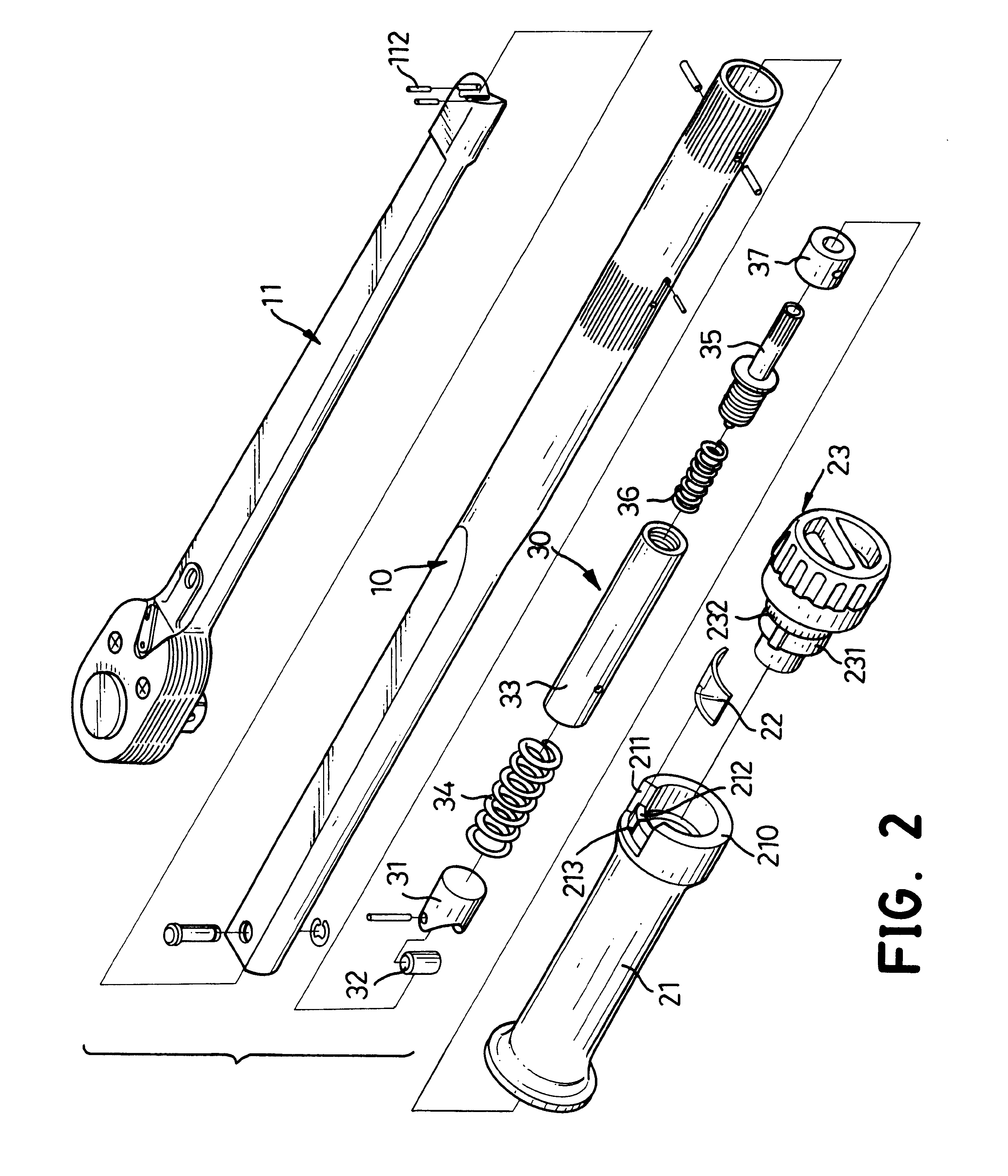
With reference to FIGS. 1 and 2, a torque wrench in accordance with the present invention comprises a shank (10), an arm (11), a torque-adjusting device (30), an adjusting knob (23) and a handle (21). The shank (10) is a tubular member and has a first end and a second end. The arm (11) is inserted into the first end of the shank (10). An engaging portion is mounted at the exposed end of the arm (11) to fit with specific sleeves that are used to rotate desired fasteners.

The torque-adjusting device (30) is mounted in the shank (10) and is connected to the arm (11). The torque-adjusting device (30) comprises a cylinder (32), a cylinder mount (31), a pushing sleeve (33), two biasing members (34,36), a pushing bar (35) and a collar (37). The cylinder (32) is attached to the cylinder mount (31) with a pivot (not numbered) and abuts the end of the arm (11) at a position between two pins (112). The first biasing member (34) is mounted between the cylinder mount (31) and the pushing sleeve (...


PUM


Abstract

A torque wrench has a shank, an arm, a torque-adjusting device, a handle and an adjusting knob. The handle is mounted around one end of the shank and has a mouth. A window is defined in the periphery of the mouth. The adjusting knob is rotatably attached to the shank. A stepped protrusion formed on the adjusting knob is connected to the torque-adjusting device and is received in the mouth. A scale is formed on the outer periphery of the stepped protrusion and corresponds to the window. An index line is formed on the handle and corresponds to the scale. Accordingly, the scale can be easily read through the window with the index line. The mouth can provide a protecting effect to the scale to keep the scale from being worn off, such that the useful life of the torque wrench is prolonged.

Description

1. Field of the InventionThe present invention relates to a torque wrench, and more particularly to a torque wrench with an easy-read scale.2. Description of Related ArtTo provide a precise tightening to a fastener, a torque wrench is used to tighten the fastener to secure two objects together with a desired torque. An adjusting knob is mounted on the torque wrench to adjust the torque that the wrench applies to the fastener. To show the amount of torque to the user, a scale is mounted around the outer periphery of the adjusting knob, and a pointer is mounted on the shank of the wrench to point out the number on the scale. Consequently, the user can read the torque provided by the wrench from the pointed number on the scale.However, as the scale of the conventional torque wrench is exposed on the outer periphery of the adjusting knob, the scale is easily worn off when the user rotates the adjusting knob. The scale will lose its indicating function after a long time of use.To overcom...

Claims


Application Information

Patent Timeline
Patent Type & Authority Patents(United States)
IPC IPC(8): B25B23/142B25B23/14
CPCB25B23/1427
Inventor HSIEH, CHIH-CHING
Owner HSIEH CHIH CHING
Why Eureka
Try Eureka