Hall effect seat belt tension sensor

a seat belt and sensor technology, applied in the direction of instruments, pedestrian/occupant safety arrangements, force/torque/work measurement apparatus, etc., can solve the problems of small children, small people may be injured by and the inflating of the bag has a higher chance of injury

Inactive Publication Date: 2004-05-04
CTS CORP ELKHART
View PDF31 Cites 40 Cited by
  • Summary
  • Abstract
  • Description
  • Claims
  • Application Information

AI Technical Summary

Problems solved by technology

However, since their incorporation into automobiles, a problem has existed with people of smaller size and small children.
A smaller person may be injured by a bag inflating at this higher inflation force.
A smaller person is more likely to be sitting close to the dashboard and would therefore stand a higher chance of being injured by the impact of the inflating bag, as opposed to the passenger hitting the fully inflated bag to absorb the impact of the accident.
An average-sized person can also be injured by an airbag inflation if they are leaning forward, as for example, if they are adjusting the radio.
However, if the seat belt is unduly tightened, it can place an additional downward force on the passenger, creating an erroneous weight reading.

Method used


Image

  • Hall effect seat belt tension sensor
  • Hall effect seat belt tension sensor
  • Hall effect seat belt tension sensor

Examples


Embodiment Construction

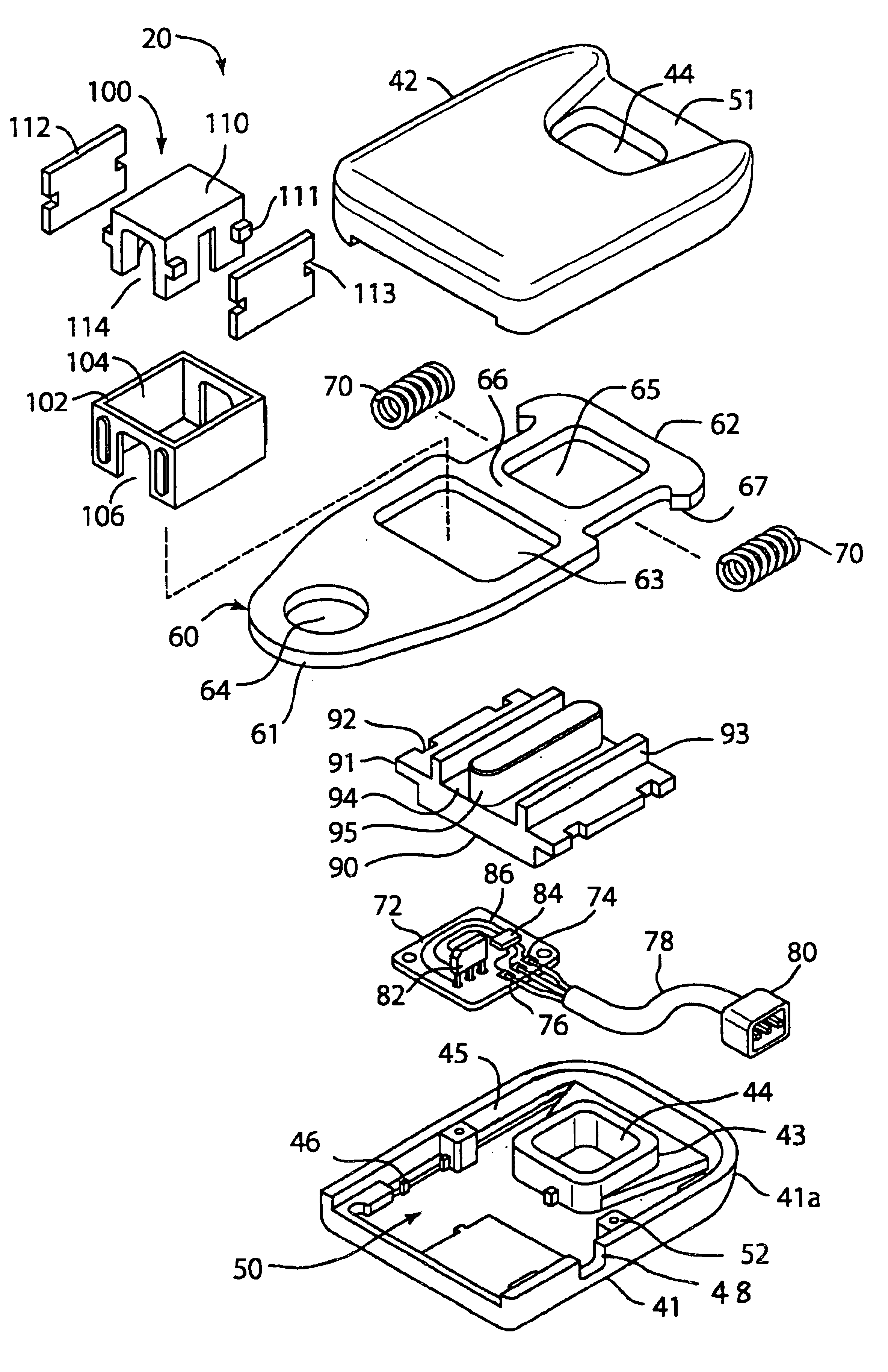
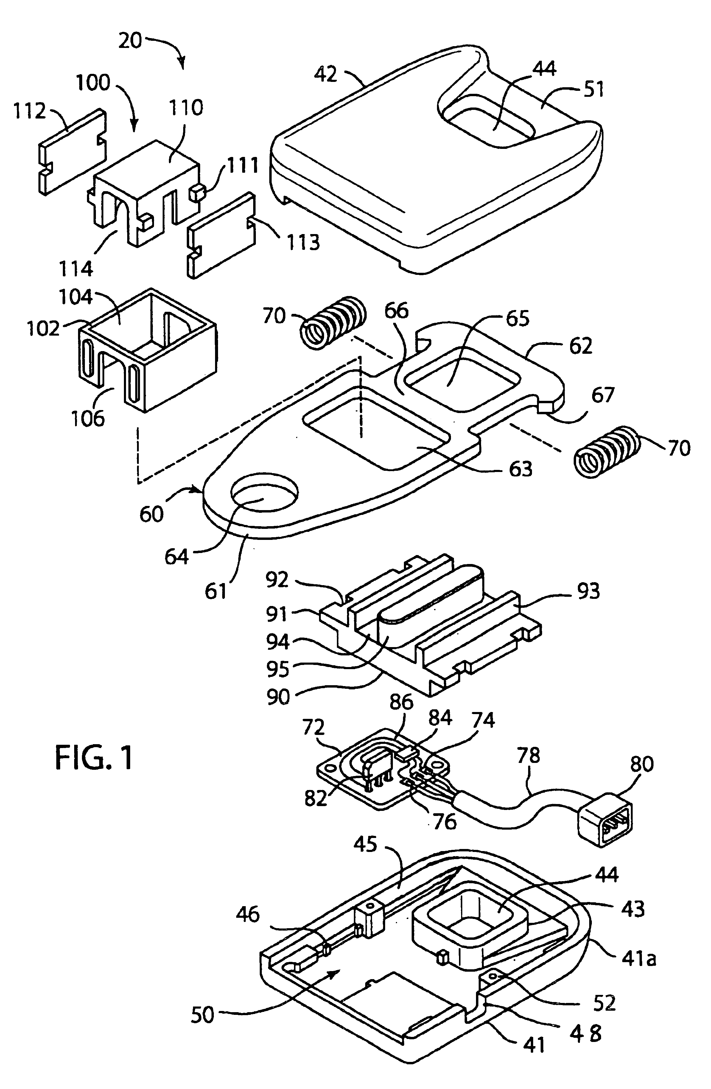
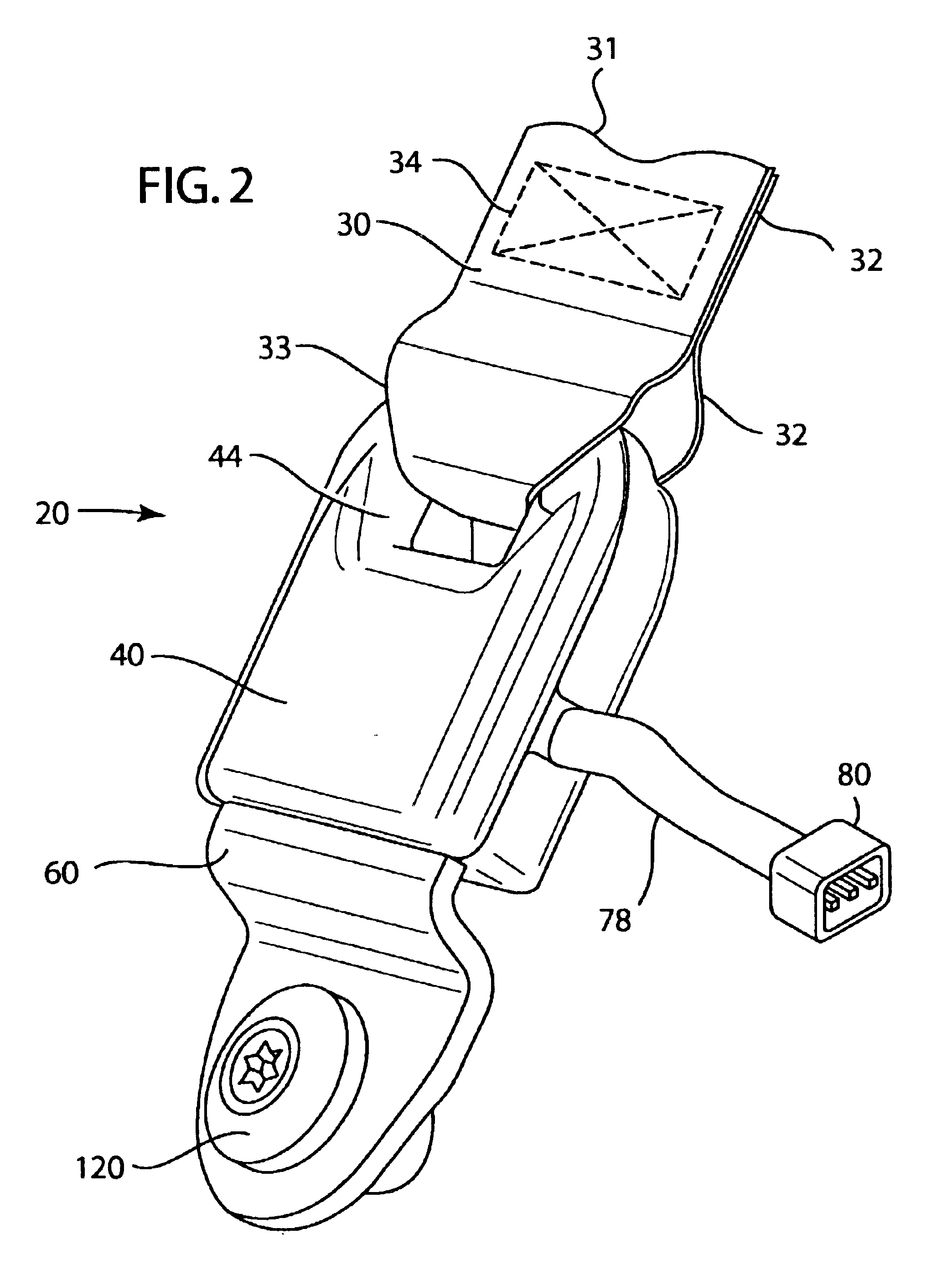
The present invention is a seat belt tension sensor. Referring to FIGS. 1 and 2, a seat belt tension sensor assembly 20 shown., Assembly 20 has a housing 40 and anchor plate 60. Housing 40 is fastened between a seat belt webbing 30 and a structural part of the vehicle such as a floor (not shown). The belt webbing 30 has an end 31, an end 32, a belt loop 33 and stitching 34 that retains end 32.

Housing 40 has a bottom portion 41, top portion 42, flange 43, hole 44, spring channel 45, posts 46, groove 48. A cavity 50 is located within housing 40. The bottom portion 41 and top portion 42 connect together and are held together by ultrasonic welding along lip 41 A. Housing portion 42 has a recess or narrow portion 51 on an end of the housing where the seat belt wraps around.

Anchor plate 60 is loosely fitted within housing 40. Anchor plate 60 includes ends 61 and 62, a cutout 63, apertures 64 and 65. Arm 66 extends between aperture 65 and cutout 63. A projection 67 extends from end 62. The...


PUM

PropertyMeasurementUnit
tensionaaaaaaaaaa
magnetic fieldaaaaaaaaaa
tensile forceaaaaaaaaaa

Abstract

A hall effect seat belt tension sensor for a vehicle. The sensor has a housing mounted to a seat belt. An anchor plate is mounted between the seat belt and a fixed point on a vehicle. The anchor plate is partially mounted in housing. A spring is mounted between the housing and the anchor plate. Tension on the seat belt causes the anchor plate to move relative to the housing. A magnetic field generator is mounted to the anchor plate. The magnetic field generator moves as the anchor plate moves. A magnetic field sensor is mounted to the housing. The sensor generates an electrical signal in response to movement of the magnetic field generator.

Description

BACKGROUND1. Field of the InventionThis invention relates to an automobile sensor for detecting the magnitude of a tensile force in a seat belt used in a car seat, and in particular to a sensor that can detect the magnitude of tension in a seat belt and provide an electrical signal that is representative of the magnitude of tensile force.2. Description of the Related ArtAir bags have been heralded for their ability to reduce injuries and save lives. However, since their incorporation into automobiles, a problem has existed with people of smaller size and small children. Air bags are designed to cushion the impact of occupants and thus reduce the injuries suffered. However, the force needed to properly cushion the occupant varies based on the size and position of the person.For example, a larger person requires the bag to inflate faster and thus with more force. A smaller person may be injured by a bag inflating at this higher inflation force. A smaller person is more likely to be si...

Claims


Application Information

Patent Timeline
Patent Type & Authority Patents(United States)
IPC IPC(8): B60R22/18B60R21/01B60R21/015
CPCB60R22/18B60R21/0155
Inventor KAIJALA, MURRAYTEETERS, DALE
Owner CTS CORP ELKHART
Why Eureka
Try Eureka