Vehicle air conditioner

a technology for air conditioners and vehicles, applied in vehicle components, vehicle heating/cooling devices, railway heating/cooling, etc., can solve the problems of difficult to freely set the flow ratio between air blown toward the upper air blown toward the lower side of the passenger compartment in a bi-level mod

Inactive Publication Date: 2004-05-18
DENSO CORP
View PDF16 Cites 9 Cited by
  • Summary
  • Abstract
  • Description
  • Claims
  • Application Information

AI Technical Summary

Benefits of technology

According to the present invention, in a vehicle air conditioner, a case defining an air passage through which air flows into a passenger compartment includes a first wall portion positioned at one side when being viewed in a flow direction of air passing through a cooling heat exchanger and a heating heat exchanger, and a second wall portion extending in a direction approximately perpendicular to the first wall portion. A first opening from which air is blown toward one side in the passenger compartment is provided in the first wall portion, and a second opening from which air is blown toward an another side in the passenger compartment is provided in the second wall portion. A first door is disposed the case for opening and closing the first opening, and a second door disposed in the case for opening and closing the second opening. The first door includes a plate member having a door surface moved along a surface of the first wall portion, and is disposed to open and close the first opening by a movement of the door surface along the surface of the first wall portion. Because the first door is constructed by a plate member moved along the surface of the first wall portion of the case, an arrangement space of the first door can be reduced, and an air flow in the case is not disturbed by the movement of the first door. Accordingly, a disturbance of the air flow in the case can be prevented, while the size of the case can be reduced.
Preferably, the first opening is provided within an area of an air mixing portion when being viewed from an opening direction of the first opening in the first wall portion. Therefore, air can be readily directly introduced into the first opening from the air mixing portion. Thus, air flow resistance can be reduced and the air flow amount introduced into the first opening can be increased, while air-flow noise can be reduced.
The first wall portion is provided at both sides of the cooling heat exchanger and the heating heat exchanger, the first opening provided in the first wall portion has two openings parts provided at both sides of the cooling heat exchanger and the heating heat exchanger to correspond to the first wall portion, and the first door has two door members for opening and closing the two opening parts of the first opening, respectively. In addition, the first door and the second door are disposed in such a manner that an operation locus of the first door is overlapped with an operation locus of the second door when being viewed from a direction perpendicular to the door surface of the first door, and the second door is disposed to be operated between the two door members of the first door to have a predetermined clearance between the second door and each door member of the first door in the direction perpendicular to the door surface of the first door. Accordingly, the arrangement space of the first and second doors can be reduced while an interference between the first and second door can be prevented.
Preferably, the first door is disposed to be rotatable around a first rotation shaft provided in the case, the second door is disposed to be rotatable around a second rotation shaft provided in the case, and each of the first rotation shaft and the second rotation shaft is disposed to extend in a direction parallel to the direction perpendicular to the door surface of the first door. Further, the first opening is formed into an approximate fan shape, the first door is formed into an approximate fan shape corresponding to the shape of the first opening, the approximate fan shape of the first opening has an outer peripheral portion having approximate arc shape, a radius center of the approximate fan shape is set at a side opposite to second rotation shaft of the second door relative to the outer peripheral portion, and the first shaft of the first door is disposed at a position corresponding the radius center of the approximate fan shape of the first opening. Accordingly, an interference between the first door and the second door can be effectively prevented while the arrangement space of the first and second doors can be further reduced.

Problems solved by technology

However, because the plural air-outlet openings are opened and closed by using only the one rotary door, each arrangement position and each size of the air-outlet openings are restricted.
Accordingly, each air amount blown from the air-outlet openings cannot be freely changed, and it is difficult to freely set a flow ratio between air blown toward an upper side of a passenger compartment and air blown toward a lower side of the passenger compartment in a bi-level mode.
However, when the plate-like doors and the rotary door are simply combined in the case, an interference between a rotation operation of the rotary door and a rotation operation of the plate doors may be caused, and air flow disturbance and a noise may be caused.

Method used


Image

  • Vehicle air conditioner
  • Vehicle air conditioner
  • Vehicle air conditioner

Examples


first embodiment

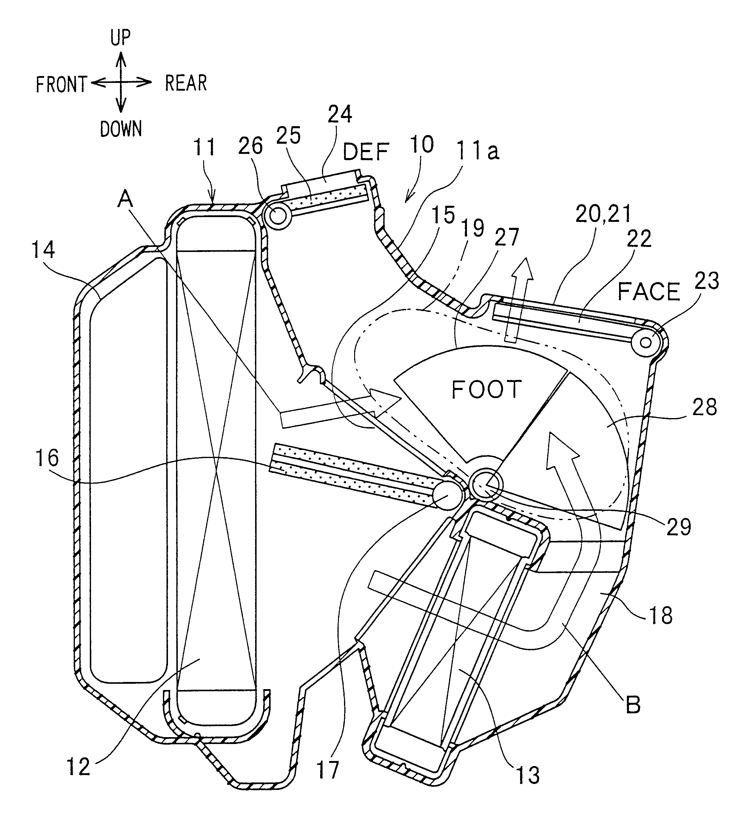
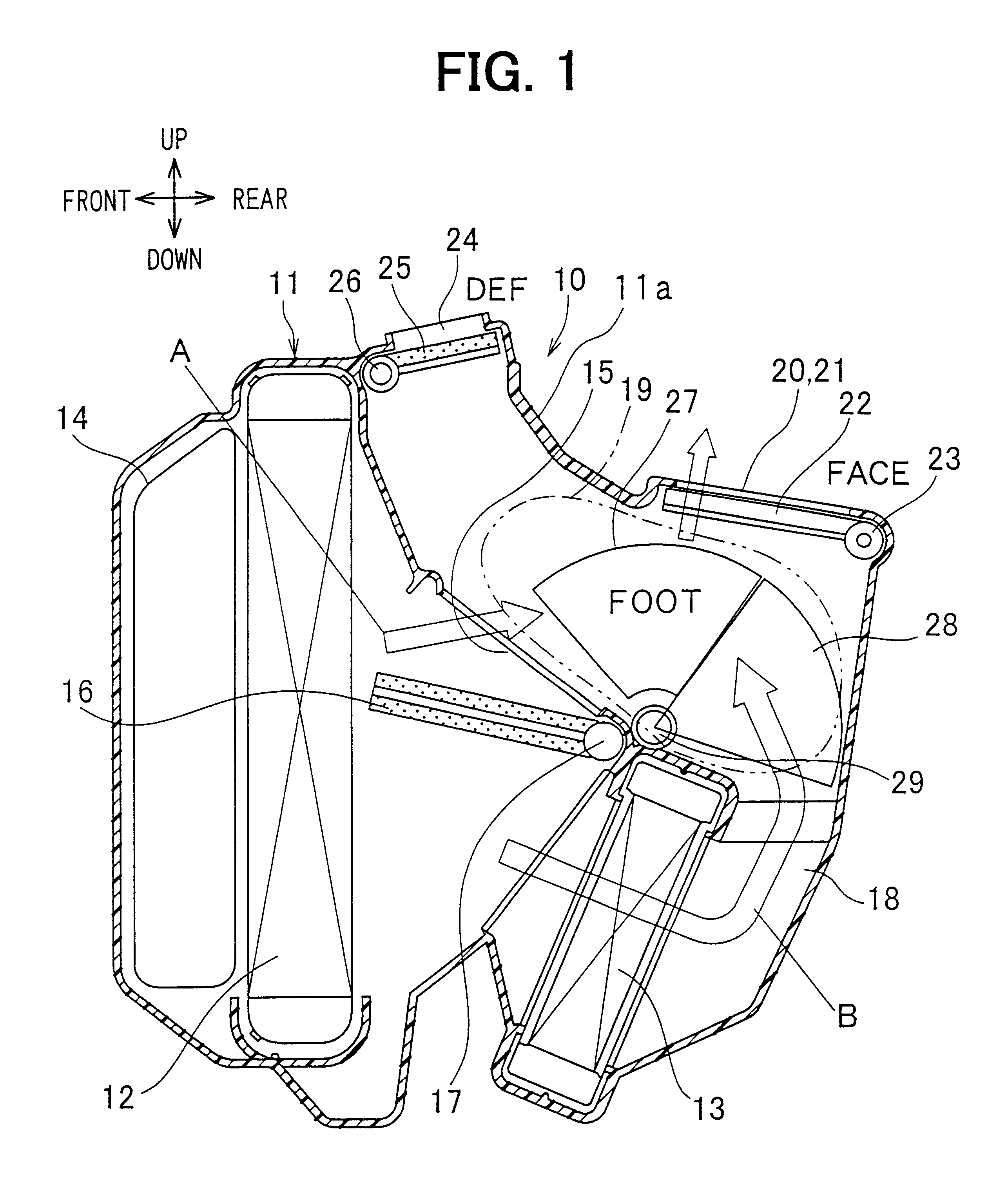
The air mixing door 16 is integrally connected to a rotation shaft 17 disposed approximately in a horizontal direction (e.g., vehicle width direction). The air mixing door 16 is disposed to be rotatable around the rotation shaft 17. In the first embodiment, by the flow ratio adjustment of the air mixing door 16, the temperature of air blown into the passenger compartment can be adjusted.

The rotation shaft 17 is rotatably supported in the air conditioning case 11. One end of the rotation shaft 17 protrudes outside the air conditioning case 11, and is connected to an actuator using a servomotor through a link mechanism or is connected to a manual operation mechanism, so that a rotation position of the air mixing door 16 is adjusted by the actuator or an manual operation mechanism.

A warm air passage 18 extending from an air outlet side of the heater core 13 toward upwardly is provided at a downstream air side of the heater core 13. Accordingly, warm air from the warm air passage 18 and...

second embodiment

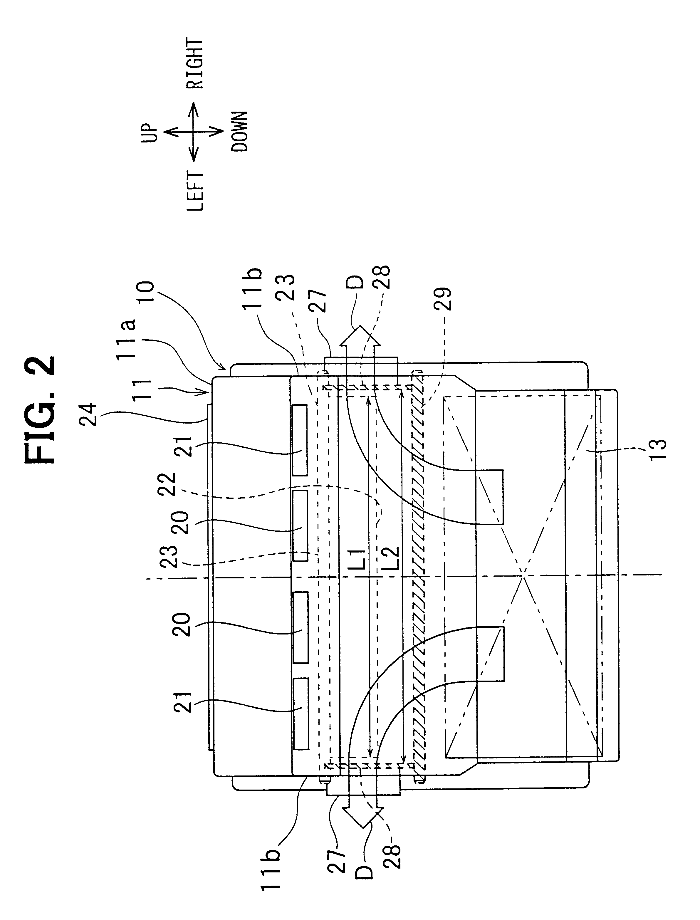
According to the present invention, when the foot opening 27 is fully closed by the foot door 28, the first seal member 31 of the periphery protrusion portion 28b having an approximate U shape of the foot door 28 press-contacts the first seal surface S1 on the inner side of the inside protrusion portion 27a of the foot opening 27, and the second seal member 32 of the side portion 28c of the foot door 28 press-contacts the second seal surface S2 on the outside of the inside protrusion portion 27a in the foot opening 27. Therefore, when the foot opening 27 is fully closed, air-sealing performance can be improved.

In the second embodiment, the other parts are similar to those of the above described first embodiment, and detail explanation is omitted. Accordingly, in the second embodiment, the advantage described in the first embodiment can be obtained.

Although the present invention has been fully described in connection with the preferred embodiments thereof with reference to the accomp...


PUM


Abstract

In a vehicle air conditioner, two foot openings are provided in right and left wall portions of a case, and are opened and closed by two foot doors, respectively. Each door surface of the foot doors is moved along a surface of the right and left wall portions for opening and closing the foot openings. A face opening is provided in a top wall part of the case to be opened an closed by a face door. An operation locus of the foot doors is overlapped with that of the face door when being viewed from a direction perpendicular to the door surface of the foot door, while the face door is operated between the foot doors to have a clearance between the face door and each foot door.

Description

1. Field of the InventionThe present invention relates to a vehicle air conditioner with an improvement of an air passage switching structure.2. Description of Related ArtIn a conventional vehicle air conditioner described in JP-A-9-150620, a cylindrical rotary door used as an air outlet mode switching door is rotatably disposed in a case. Communication ports are provided on a part of a cylindrical surface and two end surfaces in an axial direction of the cylindrical rotary door, so that plural air-outlet openings of the case can be selectively opened and closed by rotation operation of the rotary door. However, because the plural air-outlet openings are opened and closed by using only the one rotary door, each arrangement position and each size of the air-outlet openings are restricted. Accordingly, each air amount blown from the air-outlet openings cannot be freely changed, and it is difficult to freely set a flow ratio between air blown toward an upper side of a passenger compart...

Claims


Application Information

Patent Timeline
Patent Type & Authority Patents(United States)
IPC IPC(8): B60H1/00
CPCB60H1/00064B60H1/00685B60H2001/00192B60H1/00
Inventor NATSUME, TAKUYATOKUNAGA, TAKAHIRO
Owner DENSO CORP
Why Eureka
Try Eureka