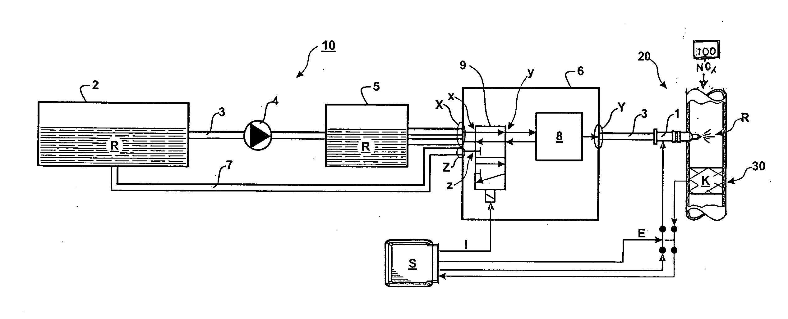
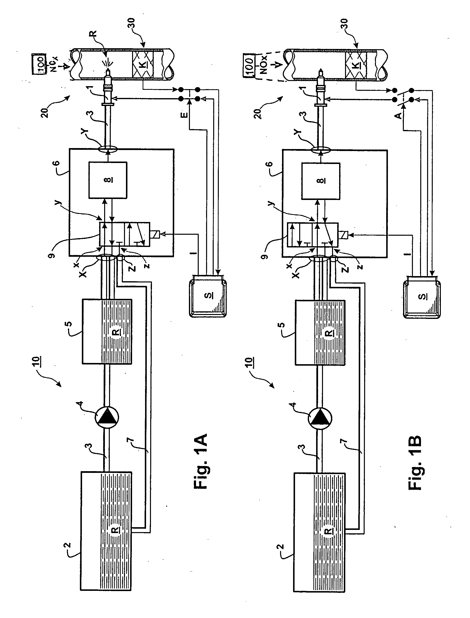
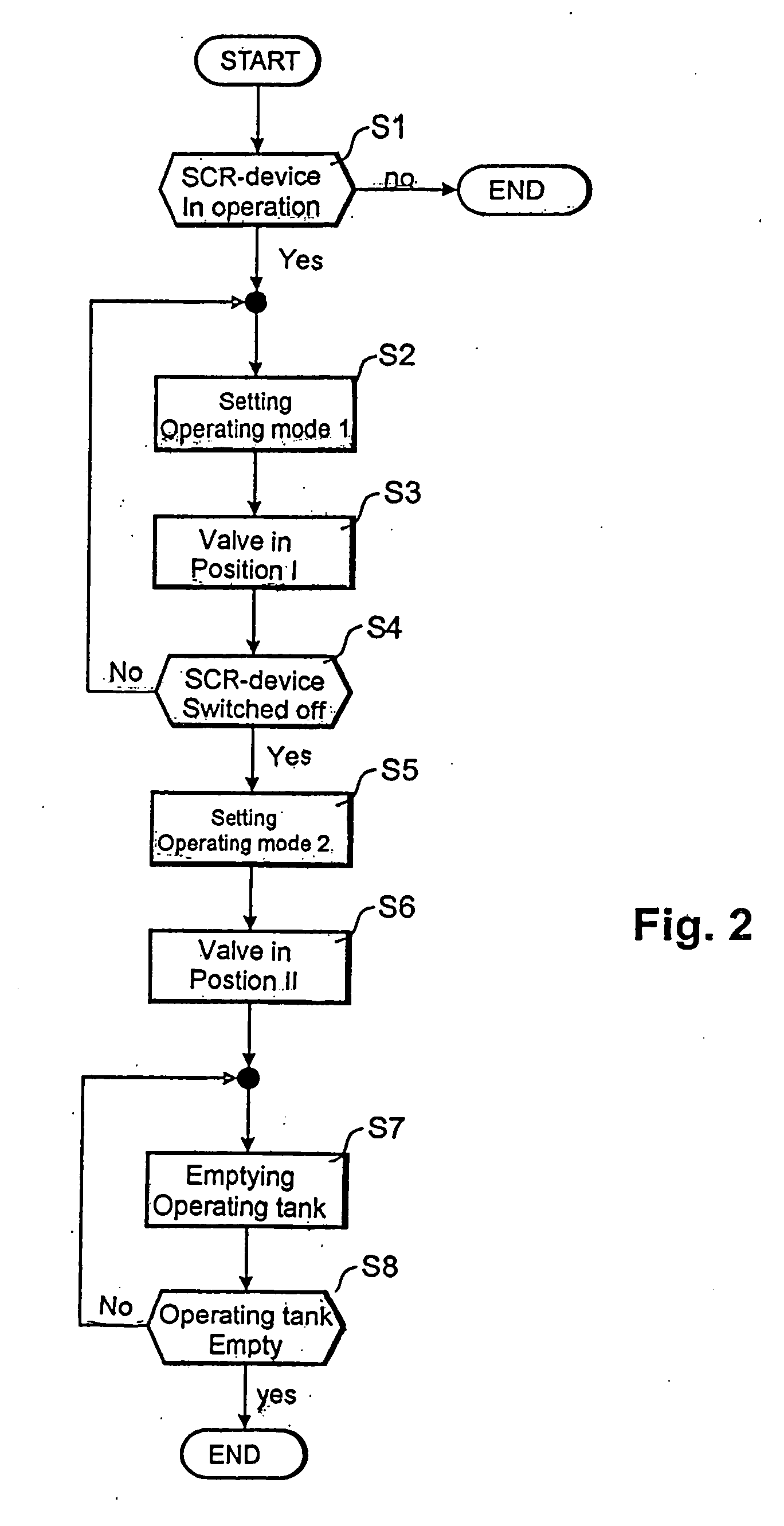
[0012]In this way, in a supply arrangement according to the invention, heating of the operating tank is not necessary since it is emptied during the second mode of operation. Basically, the concept according to the invention results in savings of components while utilizing synergistically existing components of a reducing agent supply arrangement. In accordance with the invention, the dosing device which is present anyway is used for the transfer of the reducing agent from the operating tank via the return line to the storage tank. In addition, the concept according to the invention has been shown to be particularly safe and energy-efficient. In a known reducing agent supply arrangement with a heating structure for example, a supply pump needs to run also after shut-down of an internal
combustion engine—even though for a short time—in order to achieve a pressure compensation between the supply arrangement and the exhaust gas system. Continued operation of a supply pump after engine
shut down however is basically unsafe and also diminishes comfort because of the
noise generated thereby. The use of heating-based reducing agent supply arrangements for internal
combustion engines in motor vehicles is therefore limited.
[0013]Furthermore, the concept of the invention has been found to be particularly advantageous also for use in other types of internal
combustion engines, particularly in large Diesel engines. In particular in connection with large Diesel engines with outputs of 2000 KW to 4000 KW, it is very advantageous if the need for heating arrangements can be omitted. An operating tank for reducing agents in large Diesel engines has for example a volume in the area of 100
liter. Such a tank would require a heat input of at least 5 KW in order to liquefy a frozen operating tank before startup of an engine that requires at least a one-hour heating period which is eliminated with the concept according to the invention. With the present concept, also high electric
voltage potentials, thick
electric cables and excessive consumption of coolants are not needed-especially in connection with large Diesel engines which otherwise would be needed for the heating arrangement. The concept of the invention is altogether comparatively simple and highly efficient. There are no installation space limits. In particular, the arrangement of the operating tank for the reducing agent is variable. Since a freezing danger is safely eliminated the components of the supply arrangement do not need to be pressure resistant since no compensation space for accommodating volume expansions as a result of freezing will occur.
[0014]As particularly advantageous the concept according to the invention was found in its application in connection with large Diesel engines for power generation operation that is specifically with Diesel power generator units. The use of large Diesel engines including the inventive concept in power generator units is particularly advantageous since on one hand the comfort requirements of large Diesel engines in a power generator unit are of subservient importance and, on the other hand, the operation of the dosing arrangement after engine shutdown is generally not problematic.
[0015]In connection with a particularly advantageous embodiment of the invention, the dosing arrangement can be switched between two operating
modes. Preferably, the dosing arrangement includes a
directional valve to which the supply line and the return line are connected. The dosing arrangement advantageously also includes a dosing pump. Under the control of the
directional valve, the solution containing the reducing agent can be directed via the directional valve in a first operating mode to the supply line and in a second operating mode to the return line. Advantageously, the dosing arrangement includes a dosing pump which is combined with the directional valve. The directional valve may also be realized by the dosing pump. It is particularly advantageous if the directional valve is arranged in the supply line between the operating tank and the dosing pump. This provides for a particularly advantageous flow pattern of the solution containing the reducing agent in the first and the second mode of operation in that, by means of the dosing pump, the solution containing the reducing agent is conducted in the first operating mode via the supply line to the
injector and / or the operating tank and in the second operating mode via the return line to the storage tank.
[0016]Specifically, the directional valve of the dosing arrangement is a 5 / 2 way valve with two switch positions which are switched depending on the operating mode. The arrangement may also be obtained with a 3 / 2 valve if only two instead of four connections are made available for the supply line. It is advantageous if, by means of the directional valve, in a first switching position in the first mode of operation the supply line is switched for conducting fluid in both directions while the return line is blocked. In this way, it is made sure that, during operation of an internal combustion engine, the supply of reducing agent to the exhaust system is ensured or, respectively, excess reducing agent can be returned to the operating tank. The solution containing the reducing agent is supplied in the first mode of operation preferably from the storage tank to the operating tank. To this end, advantageously in addition to the dosing pump, a supply pump is provided.
[0018]In this way, the method according to the invention permits, in the second mode of operation, a transfer of the solution containing the reducing agent to the storage tank. Preferably, the arrangement permits a total emptying of the operating tank. This has the
advantage that the supply arrangement in particular the operating tank does not need a heating device, that is a heating device can be omitted with the arrangement according to the invention.


