System and method for managing electric brakes

a technology of electric brakes and management methods, applied in the direction of braking systems, automatic initiations, transportation and packaging, etc., can solve the problems of reducing reducing traction, and reducing the traction of wheels, so as to reduce the effectiveness of electric brakes and reduce the traction. , the effect of reducing the current consumption

Inactive Publication Date: 2004-06-22
HOPKINS MFG
View PDF4 Cites 26 Cited by
  • Summary
  • Abstract
  • Description
  • Claims
  • Application Information

AI Technical Summary

Problems solved by technology

During a breakaway event, however, separation of the vehicles interrupts communication between them, making an independent emergency braking system necessary in order to stop the trailer.
Unfortunately, the prior art emergency braking system suffers from a number of serious limitations and disadvantages, including, for example, that delivering maximum current can reduce the effectiveness of the electric brakes by causing them to lock, thereby causing the wheels to skid and reducing traction.
Furthermore, once the trailer has stopped, it becomes an unnecessary and inefficient waste of current to continue to deliver maximum current to the electric brakes for the remainder of the requisite fifteen minute period because maximum current is not necessary to hold or maintain the stopped trailer in place.
Thus, in the prior art emergency braking system, maximum braking is applied throughout the requisite fifteen minute period, even though maximum braking may not provide maximum braking effectiveness while the trailer is moving and may not provide maximum power-use efficiency once the trailer has stopped.
Those with ordinary skill in the electrical arts will appreciate that delivering maximum current to both the first and second electric brakes for fifteen continuous minutes requires that the trailer battery be relatively large, heavy, and expensive in order to have sufficient charge capacity.
In contrast to the prior art systems, however, actuation of the switch does not directly electrically connect the battery to the electric brakes to deliver maximum current in a substantially unrestricted and uncontrolled manner.

Method used


Image

  • System and method for managing electric brakes
  • System and method for managing electric brakes
  • System and method for managing electric brakes

Examples


Embodiment Construction

, below.

A preferred embodiment of the present invention is described in detail below with reference to the attached drawing figures, wherein:

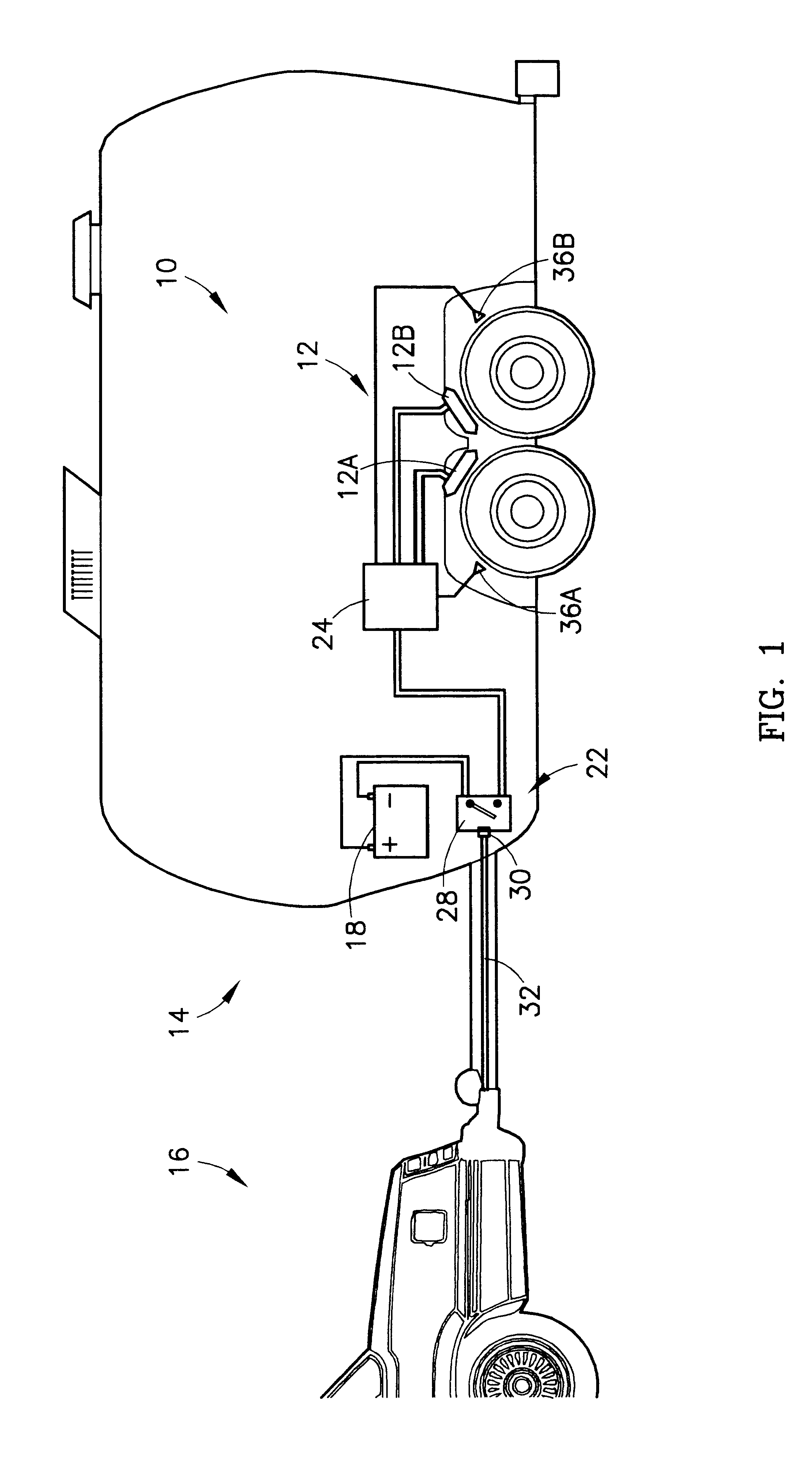
FIG. 1 is a schematic of a preferred embodiment of the emergency braking system of the present invention; and

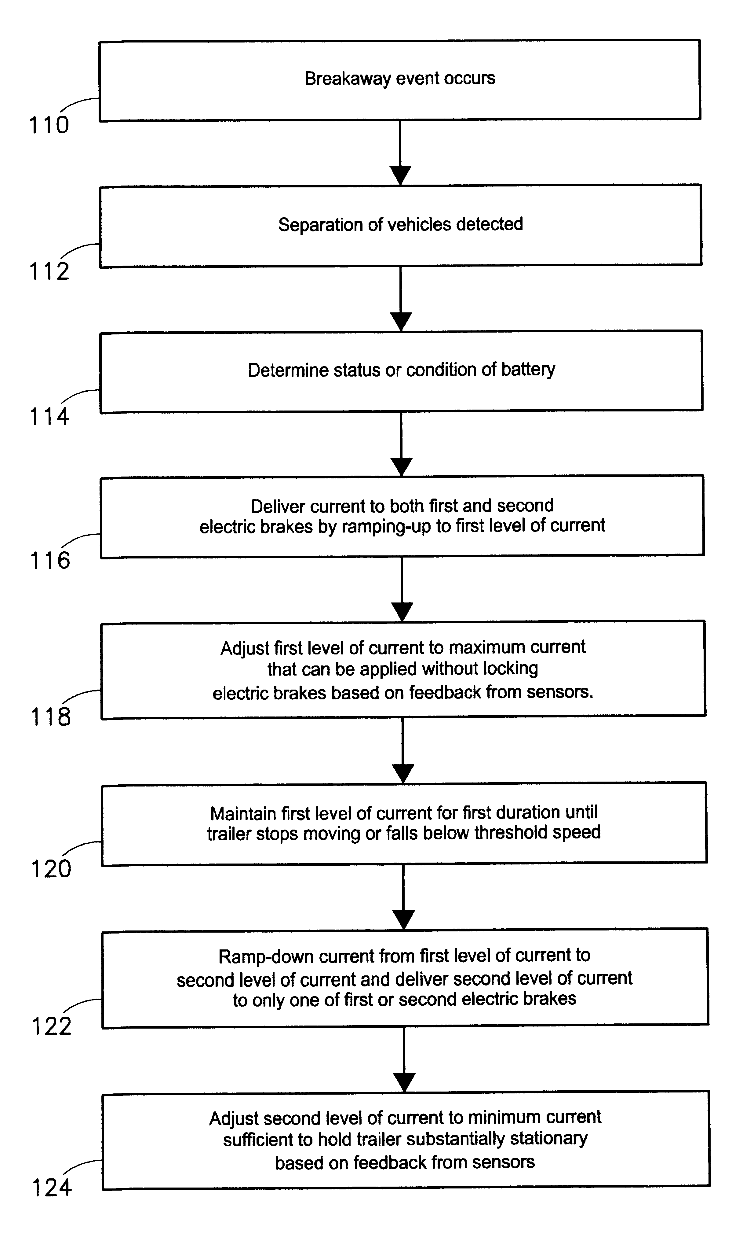
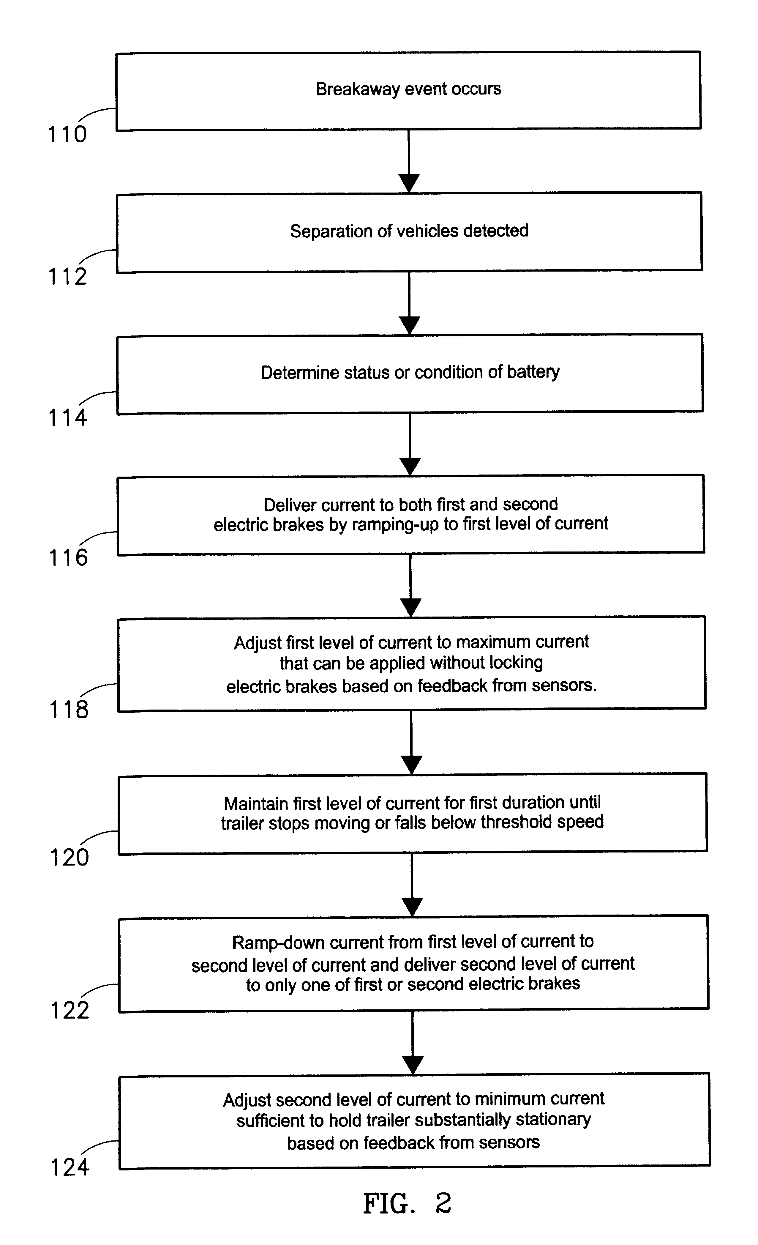
FIG. 2 is a flowchart of steps involved in operation of the emergency braking system shown in FIG. 1.

Referring to FIG. 1, an emergency braking system 10 for managing electric brakes is shown constructed in accordance with a preferred embodiment of the present invention. Broadly, the system 10 is adapted for managing an electric brake 12 in a trailer 14 or other towed vehicle during a breakaway event, in which the trailer 14 inadvertently and unsafely separates from a towing vehicle 16, by controlling or managing current flow or delivery to the electric brake 12 so as to maximize both the braking effectiveness and power-use efficiency.

As described herein, the trailer 14 includes both a first or front electric brake 12A and a second or rea...


PUM


Abstract

A system (10) and method for managing an electric brake (12) in a towed vehicle (14) during a breakaway event by managing current delivery to the electric brake (12) so as to maximize both effectiveness and efficiency. A power management module (24) delivers a first level of current for a first duration in order to stop the trailer (14), and delivers a second level of current in order to hold the trailer (14) in place. When provided with feedback, the module can actively adjust the first level of current to a maximum current while avoiding locking the electric brake (12), and to adjust the second level of current to a minimum current sufficient to hold the trailer (14). Additionally, front and rear electric brakes (12A,12B) can be managed differently or independently in order to achieve the most effective and efficient result.

Description

1. Field of the InventionThe present invention relates broadly to systems and methods for managing electric brakes in trailers or other towed vehicles. More particularly, the present invention concerns a system and method for managing an electric brake in a trailer or other towed vehicle during a breakaway event, in which the towed vehicle separates from a towing vehicle, by controlling or managing current flow or delivery to the electric brake so as to maximize both effectiveness and efficiency.2. Description of the Prior ArtIt is necessary, during a breakaway event in which a trailer or other towed vehicle unexpectedly and unsafely separates of "breaks away" from a towing vehicle, to manage the operation and application of the trailer's electric brakes so as to safely stop the trailer. The trailer typically includes a first or front electric brake and a second or rear electric brake, operation of which is slaved to or otherwise controlled by the towing vehicle under normal conditi...

Claims


Application Information

Patent Timeline
Patent Type & Authority Patents(United States)
IPC IPC(8): B60T13/74B60T7/20B60T13/00
CPCB60T7/20B60T13/741
Inventor OLBERDING, LYNN M.GRAY, JONATHAN S.
Owner HOPKINS MFG
Why Eureka
Try Eureka