Production tree with multiple safety barriers

a safety barrier and production tree technology, applied in the direction of sealing/packing, drilling pipes, borehole/well accessories, etc., can solve the problem of large seal cost and large internal tree cap requirements

Inactive Publication Date: 2004-07-20
ABB VETCOGRAY
View PDF13 Cites 85 Cited by
  • Summary
  • Abstract
  • Description
  • Claims
  • Application Information

AI Technical Summary

Problems solved by technology

While workable, an internal tree cap requires a large seal that is fairly expensive.

Method used


Image

  • Production tree with multiple safety barriers
  • Production tree with multiple safety barriers
  • Production tree with multiple safety barriers

Examples


Embodiment Construction

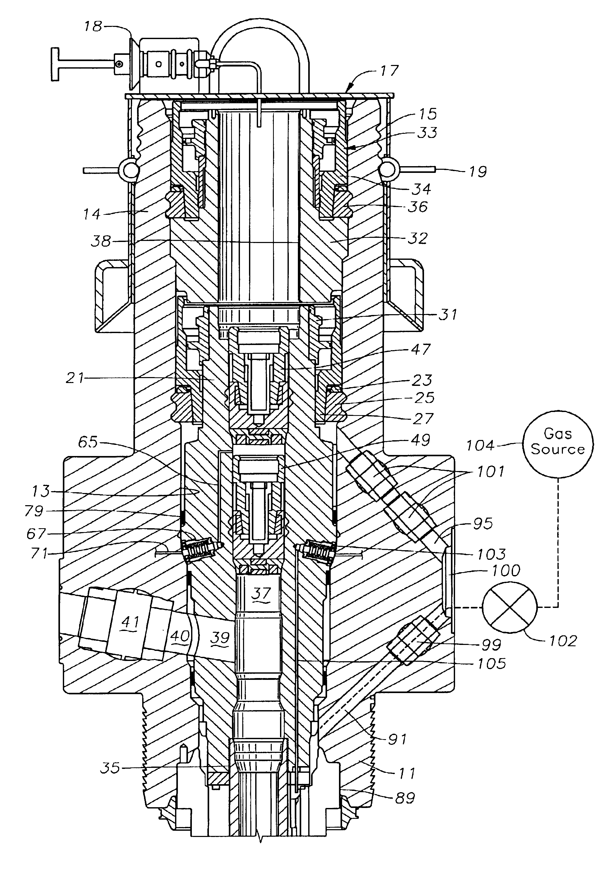
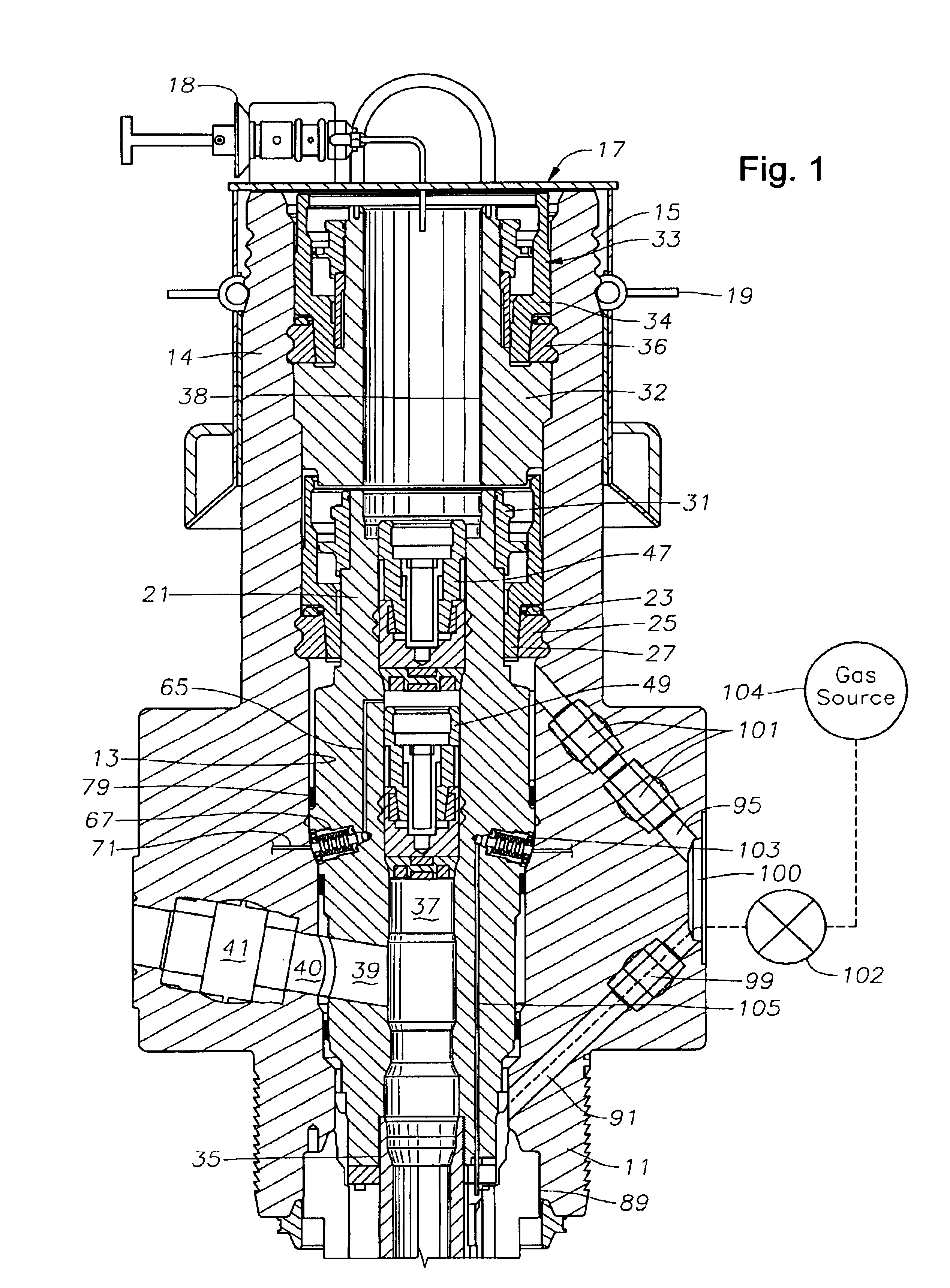
Referring to FIG. 1, production tree 11 is of a type known as a horizontal tree. The word "tree" is used broadly herein to include other variations of tubular members or wellheads located at the upper end of the well. The word "tree" is meant to also encompass a wellhead member through which at least some of the drilling may occur, which has a tubing hanger landed therein, and a lateral production flow passage. In this embodiment, tree 11 is mounted to a wellhead housing (not shown) and is typically installed after the well has been drilled and cased. Tree 11 has a vertical or axial tree bore 13 extending completely through it. The upper portion of tree 11 is a cylindrical member or mandrel 14 with a set of grooves 15 located on the exterior for connection to a drilling riser (not shown).

A removable corrosion cap assembly 17 is installed on the upper end of tree 11 after the riser is removed. A lockdown lever 19 engages grooves 15 to secure corrosion cap assembly 17 to tree 11. Alth...


PUM


Abstract

The wellhead assembly has a production tree with multiple safety barriers. A tubing hanger lands and seals in the bore of the tree. The tubing hanger has a lateral production flow passage that registers with a lateral passage in the tree. A tubing annulus passage extends upward from the tubing annulus to an exterior port. A second portion of the tubing annulus passage extends upward from the exterior port into the bore above the tubing hanger seal. The external port may be used for gas injection. If so, two closure members are located in the upper portion of the tubing annulus above the seal. The upper closure member may be either a check valve or a removable plug.

Description

1. Field of the InventionThis invention relates in general to wellhead assemblies, and in particular to a production tree with multiple safety barriers against excessive pressure.2. Description of the Prior ArtOne type of wellhead assembly particularly in a subsea well includes a wellhead housing located at the upper end of conductor pipe. Casing hangers for supporting the casing land in the wellhead housing. After the well has been drilled to total depth, a Christmas tree is lowered onto and connected to the wellhead housing.A tubing hanger lands in the tree in one type, called a horizontal tree. The tubing hanger is secured to a string of tubing that extends into the well for producing well fluids. The tubing hanger has an axial passage for production fluids, and a lateral passage extending from it that registers with a lateral passage in the tree.During installation of the tubing and tubing hanger and other operations, it may be necessary to circulate well fluid between the inter...

Claims


Application Information

Patent Timeline
Patent Type & Authority Patents(United States)
IPC IPC(8): E21B33/047E21B34/04E21B33/03E21B34/00E21B33/035E21B33/043
CPCE21B33/035E21B33/043E21B33/047E21B34/04
Inventor HUMPHREY, BERNARDGOETZ, JEFFREY P.INGRAM, KEVIN L.BRAMMER, NORMANVOSS, JR., ROBERT K.
Owner ABB VETCOGRAY
Why Eureka
Try Eureka