Electronic locator system and method

a locator and electronic technology, applied in the field of objects locators, can solve the problems of inability to locate objects in time, manual acoustic systems are unreliable, prone to failure and false responses, and require the user to keep

Inactive Publication Date: 2004-08-10
MELBOURNE DAVID J
View PDF8 Cites 74 Cited by
  • Summary
  • Abstract
  • Description
  • Claims
  • Application Information

AI Technical Summary

Problems solved by technology

While all of these "objects" offer enhancements of one kind or another, it is ironic that they also create a new challenge for users.
This is the challenge of keeping track of the location of all these objects.
Everyone has lost, mislaid, misplaced or otherwise lost track of their keys, TV remote control, or some other object, and, then spent an inordinate amount of time trying to locate the object.
However, such manual acoustic systems have proven to be unreliable and prone to failed and false responses.
A major drawback of such a system is that it requires the user to keep track of yet another object, namely the transmitter used in the locator system.
Prior art receiver / locators are frequently as bulky as the object to which they are associated.
There are other issues with respect to the perceptibility of visual or aural response indications.
For example, when an object with a receiver / locator has fallen into a couch such that any visual indicator is hidden and aural indications are muffled, the user may not be able to perceive that responsive indicator.
Or, if the lost object is in another room such that its responsive indicators are not perceivable, the user may give up their search, or continue to search in vain, without knowledge that the lost object is located nearby.

Method used


Image

  • Electronic locator system and method
  • Electronic locator system and method
  • Electronic locator system and method

Examples


Embodiment Construction

Illustrative embodiments and exemplary applications will now be described with reference to the accompanying drawings to disclose the advantageous teachings of the present invention.

While the present invention is described herein with reference to illustrative embodiments for particular applications, it should be understood that the invention is not limited thereto. Those having ordinary skill in the art and access to the teachings provided herein will recognize additional modifications, applications, and embodiments within the scope thereof and additional fields in which the present invention would be of significant utility.

People routinely misplace important personal items every day. Radio transmitters paired with receiver / locators have been attempted in the past. The latest systems use short-range radio. However, such systems require the use of a separate transmitter, which is used to locate the associated receivers. These systems have a major drawback; keeping track of the trans...


PUM


Abstract

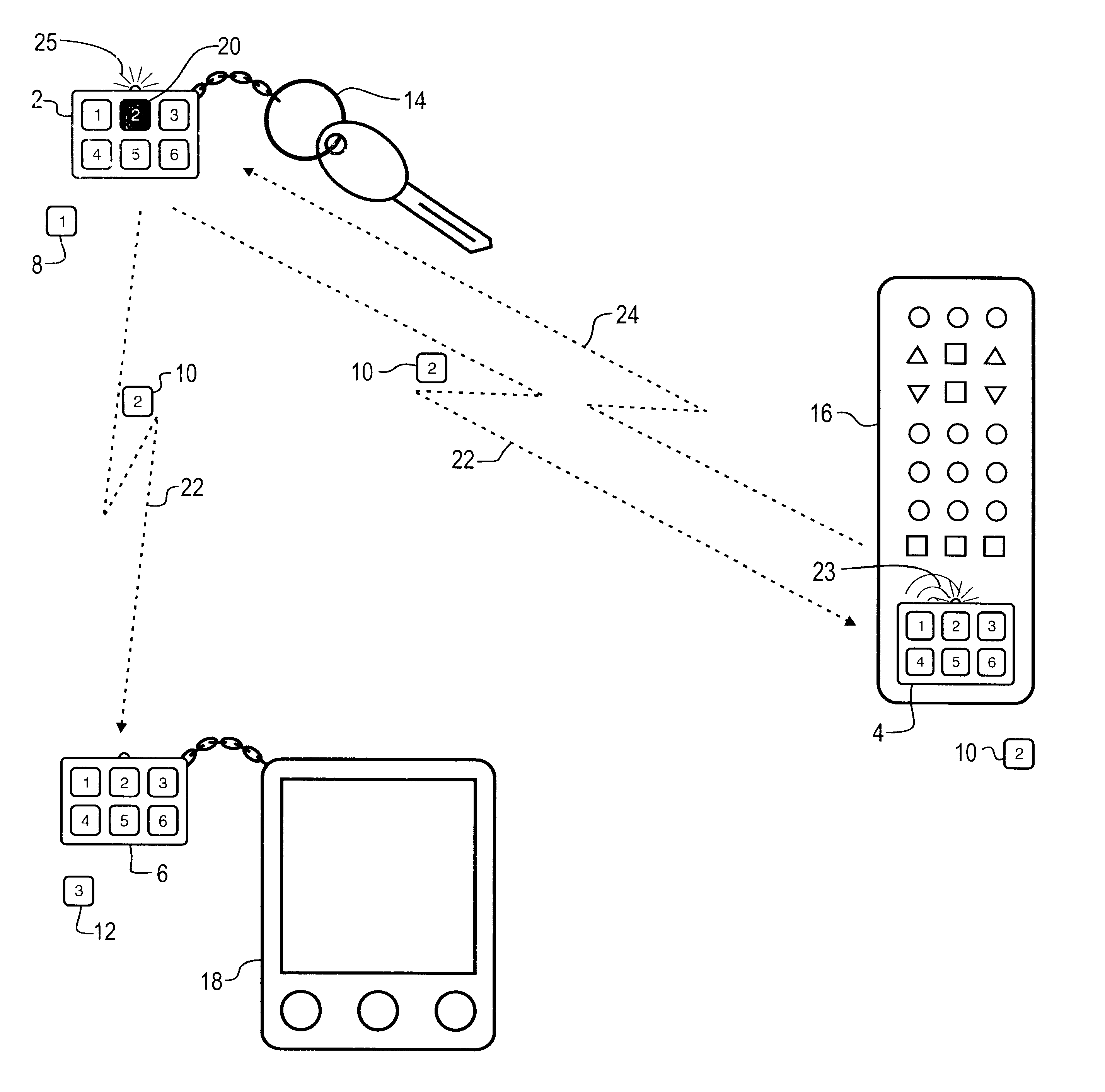
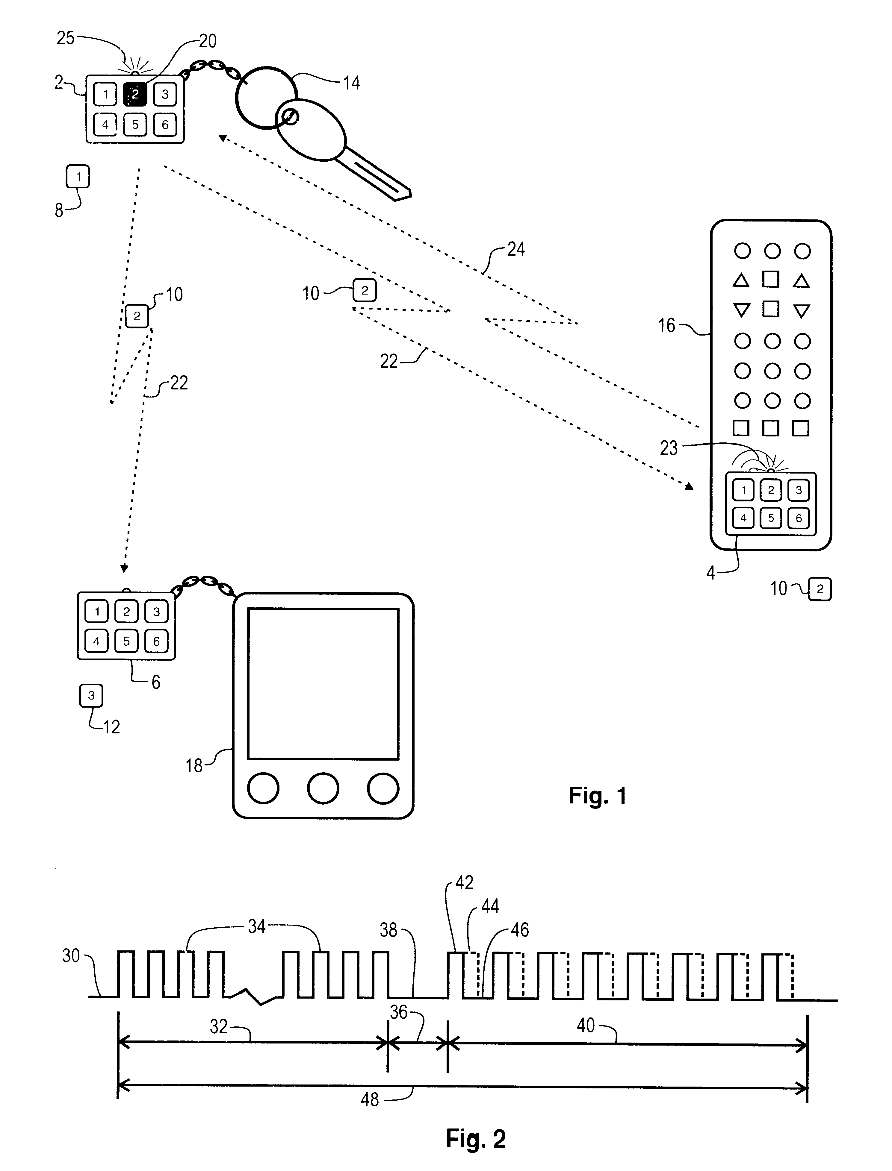
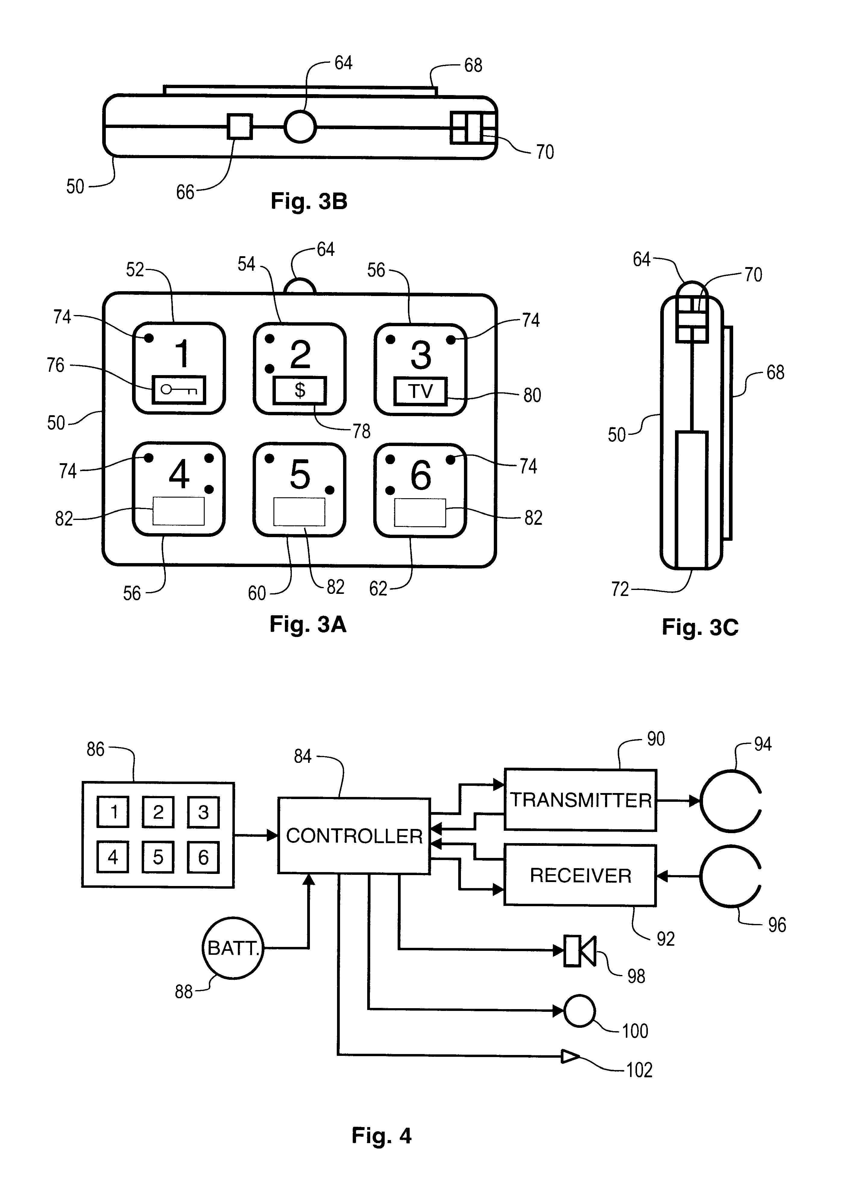
An electronic object locator apparatus and method for operation in conjunction with other functionally compliant locators. The locator includes a controller with an actuator and indicator. A transmitter is coupled to transmit search signals and found signals output from the controller, and, a receiver is coupled to output received search signals and found signals to the controller. In operation the controller outputs a first search signal upon actuation of the actuator, and activates the indicator upon receipt of a first found signal responsive to the first search signal. In addition, the controller outputs a second found signal and activates the indicator in response to receipt of a second search signal. Multiple actuators are provided to address multiple functionally compliant locators. Radio signaling is employed, and may be operated under FCC Part 15. The search signals may include both a unit identity and a series identity. Braille symbols and icons can be applied to the actuators. A programming port is supplied so that automated test and programming equipment can be employed. The locator can be built into the objects that are located by the system.

Description

1. Field of the InventionThe present invention relates to systems for locating objects. More specifically, the present invention relates to a wireless system having plural transceivers, some of which may be coupled to objects and used to locate the objects when they are not otherwise readily perceivable.2. Description of the Related ArtTechnology provides a multitude of products that enhance modem life. In the area of consumer electronics, a few examples are; the wireless remote control, the wireless or cordless telephone, personal digital assistants ("PDA"), pagers, portable computers, personal music players, audio, image, and video capture devices, and many other portable electronic devices. When one ponders the conveniences of modem life it is amazing how many portable products and devices people use everyday. Other examples include eyeglasses, watches, medicine, address directories, telephone number listings, various containers of personal objects, medical monitoring and testing...

Claims


Application Information

Patent Timeline
Patent Type & Authority Patents(United States)
IPC IPC(8): G08B21/00G08B21/24
CPCG08B21/24
Inventor MELBOURNE, DAVID J.
Owner MELBOURNE DAVID J
Why Eureka
Try Eureka