

Accumulator
a technology of accumulator and accumulator body, which is applied in the direction of machines/engines, brake systems, brake cylinders, etc., can solve the problems of difficult to completely remove the contamination, laborious cleaning, and malfunction of the accumulator
- Summary
- Abstract
- Description
- Claims
- Application Information
AI Technical Summary
Benefits of technology
Problems solved by technology
Method used
Image

Examples
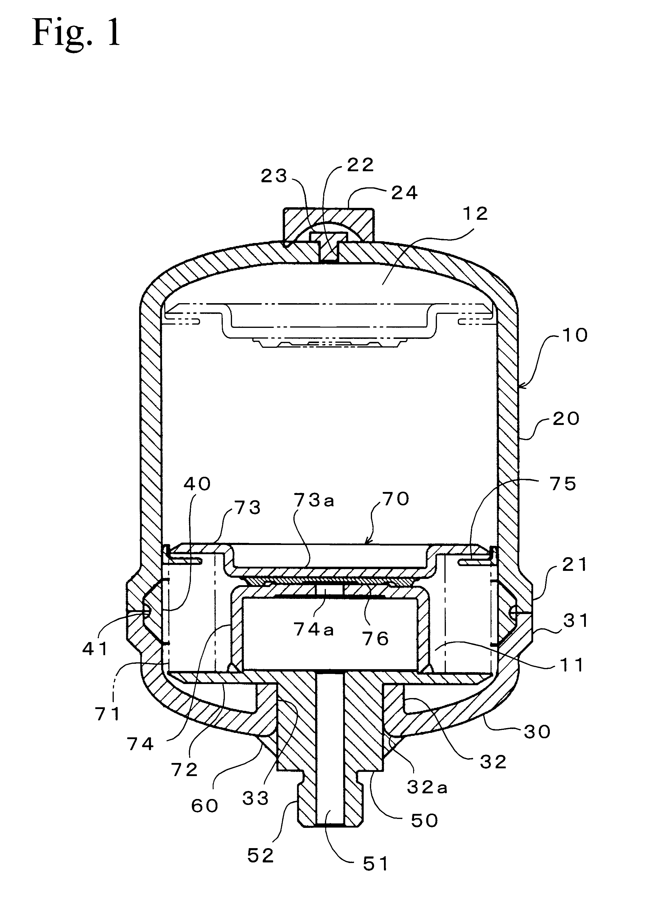
first embodiment
FIG. 1 is a cross section showing an accumulator of a first embodiment according to the invention. In FIG. 1, reference numeral 10 is a cylindrical shell forming a sealed vessel.
The shell 10 consists of a bottom shell (divided shell body) 20 as a main body and a cap shell (divided shell body) 30 which are joined to each other by welding and are divided in the axial direction. The length in the axial direction of the bottom shell 20 is longer than that of the cap shell 30. axial direction of the bottom shell 20 is longer than that of the cap shell 30. The shells 20 and 30 are made from a metal such as steel and are formed by a press to an approximately uniform thickness. The axially extending body portions of the shells 20 and 30 are joined to each other by projection welding.
A circular circumferential portion 21 or 31 projecting outward is formed at the joining end of the shells 20 and 30 around the entire circumference thereof. The end surfaces of these circular circumferential por...
second embodiment
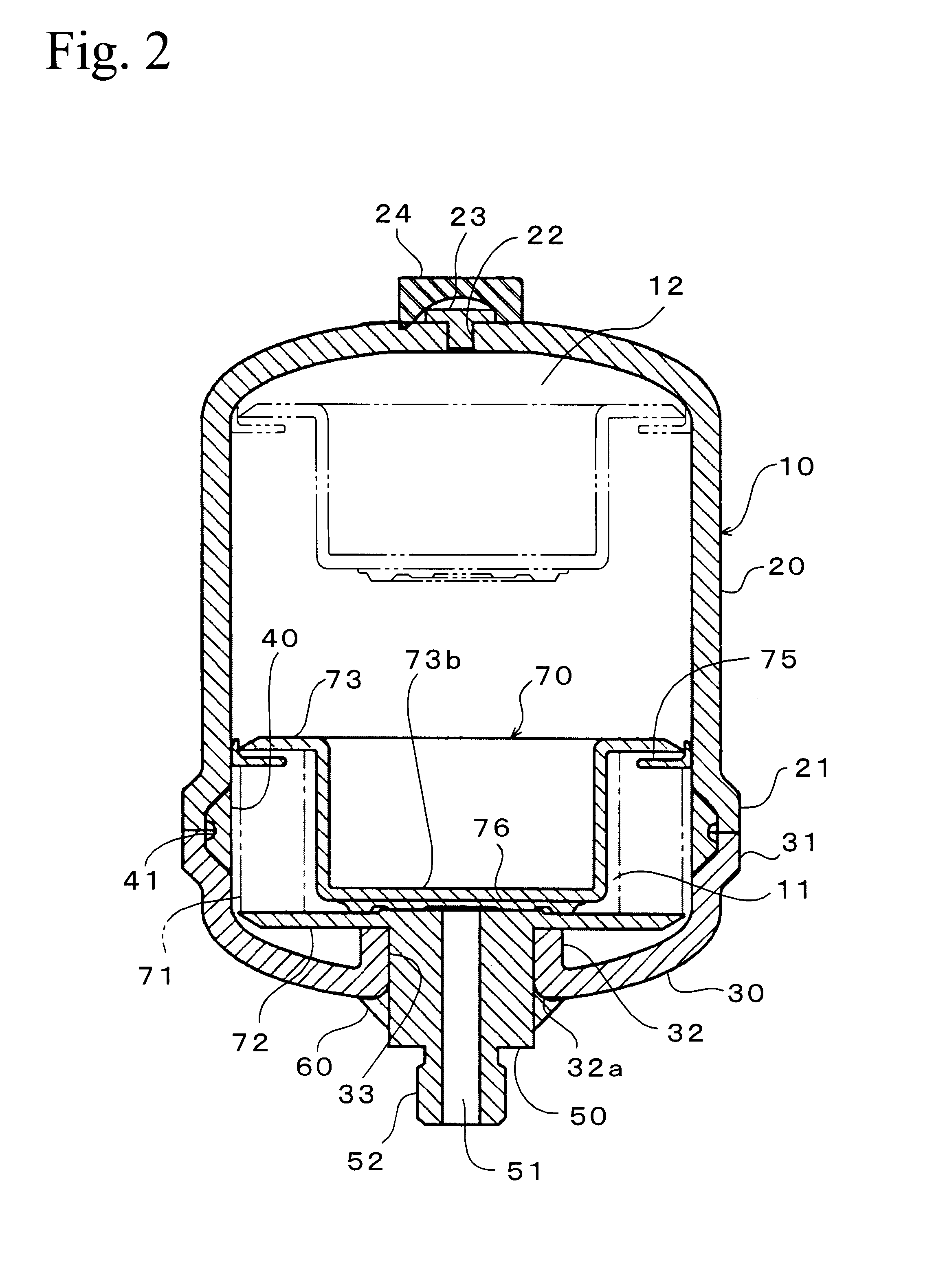
(2) Second Embodiment
A second embodiment will be explained with reference to FIG. 2 hereinafter. In FIG. 2, numerals corresponding to those in the first embodiment are attached to the same elements as in the first embodiment, and explanation thereof are omitted.
The accumulator in the embodiment has the same essential structure as the first embodiment except that the resonance box 74 in the first embodiment is not used to, and the depth of the recess 73b of the bellows cap 73 is larger than that of the recess 73a in the first embodiment. Therefore, when the bellows 71 is in the most contracted condition, a self seal 76 adhered to the inner surface of the bellows cap 73 directly closes the flow path 51 of the port 50. The two-dot chain line in FIG. 2 shows the position of the bellows cap 73 when the bellows assembly 70 is in the most expanded condition.
Similarly in the accumulator in the embodiment, the port 50 is airtightly press fitted into the cylindrical portion 32 formed in the c...
third embodiment
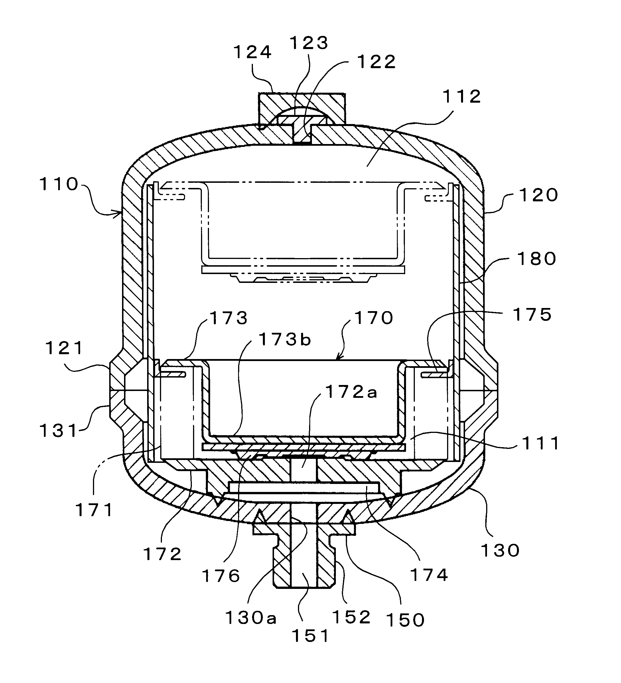
(3) Third Embodiment
FIG. 3 shows an accumulator of a third embodiment according to the invention. In FIG. 3, numerals corresponding to those in FIG. 5 are attached to the same elements as in the first embodiment, and explanations thereof are simplified or omitted.
The shell 110 consists of a bottom shell (divided shell body) 120 and a cap shell (divided shell body) 130 which are joined to each other by welding. A circular circumferential portion 121 or 131 projecting outward is formed at the joining end of the shells 120 and 130 around the entire circumference thereof. The circular circumferential portions 121 and 131 are formed for reinforcement and so as not to project a bead formed in welding both by projection welding, which is a kind of resistance welding, from the inner surface of the shell 110.
The bellows assembly (partitioning member) 170 is contained in the shell 110 so as to partition the interior of the shell 110 into a hydraulic chamber 111 and a gas chamber 112. The bell...
PUM
 Abstract
Description
Claims
Application Information