
Coaxial cable connector

a technology of coaxial cable and connector, which is applied in the direction of electrical equipment, printed circuits, and permanent deformation-induced connections, etc., can solve the problems of high time requirements, inability to conduct electrical connections with precision between the internal conductors of coaxial cables and the conductors of other cables, and connection errors during the soldering process

Inactive Publication Date: 2004-09-14
DAIICHI SEIKO CO LTD
View PDF7 Cites 67 Cited by
  • Summary
  • Abstract
  • Description
  • Claims
  • Application Information

AI Technical Summary

Benefits of technology

"The present invention provides a coaxial cable connector that simplifies the connection process of coaxial cables, reduces the time required for the connection, and minimizes the loss of connection due to failures in the connection process. The connector uses a connection terminal that retains the internal conductor of the coaxial cable with its resilience, thereby ensuring a secure and precise electrical connection. The connector can be easily connected to other cables using a separate relay connector, and the internal conductor of the coaxial cable is retained by the connection terminal. The connector is designed to prevent separation of the internal conductor from the connection terminal, even if the coaxial cable is moved."

Problems solved by technology

Nevertheless, with this electrical connection method, connection errors during the soldering process would often occur, and there is a problem in that the electrical connection between the internal conductors of coaxial cables and the conductors of other cables could not be conducted with precision.
Moreover, since the soldering process is complicated, there is a problem in that much time is required for the connection process, and that the loss is great due to failures of the connection process.
Thus, the retaining power for retaining the internal conductor is weak.
As a result, when the coaxial cable electrically connected to the connection terminal is moved due to some kind of operation, there is a problem in that the internal conductor of the coaxial cable will separate from the connection terminal and the internal conductor of the coaxial cable and the connection terminal will no longer be in electrical connection, and the electrical connection between coaxial cables and other cables cannot be established thereby.

Method used


Image

  • Coaxial cable connector
  • Coaxial cable connector
  • Coaxial cable connector

Examples


Embodiment Construction

Embodiments of the coaxial cable connector of the present invention is now described in detail in the following embodiments.

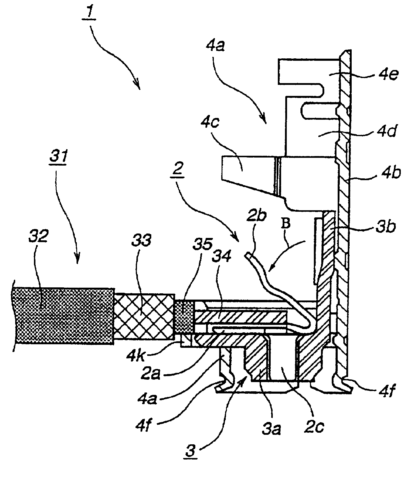
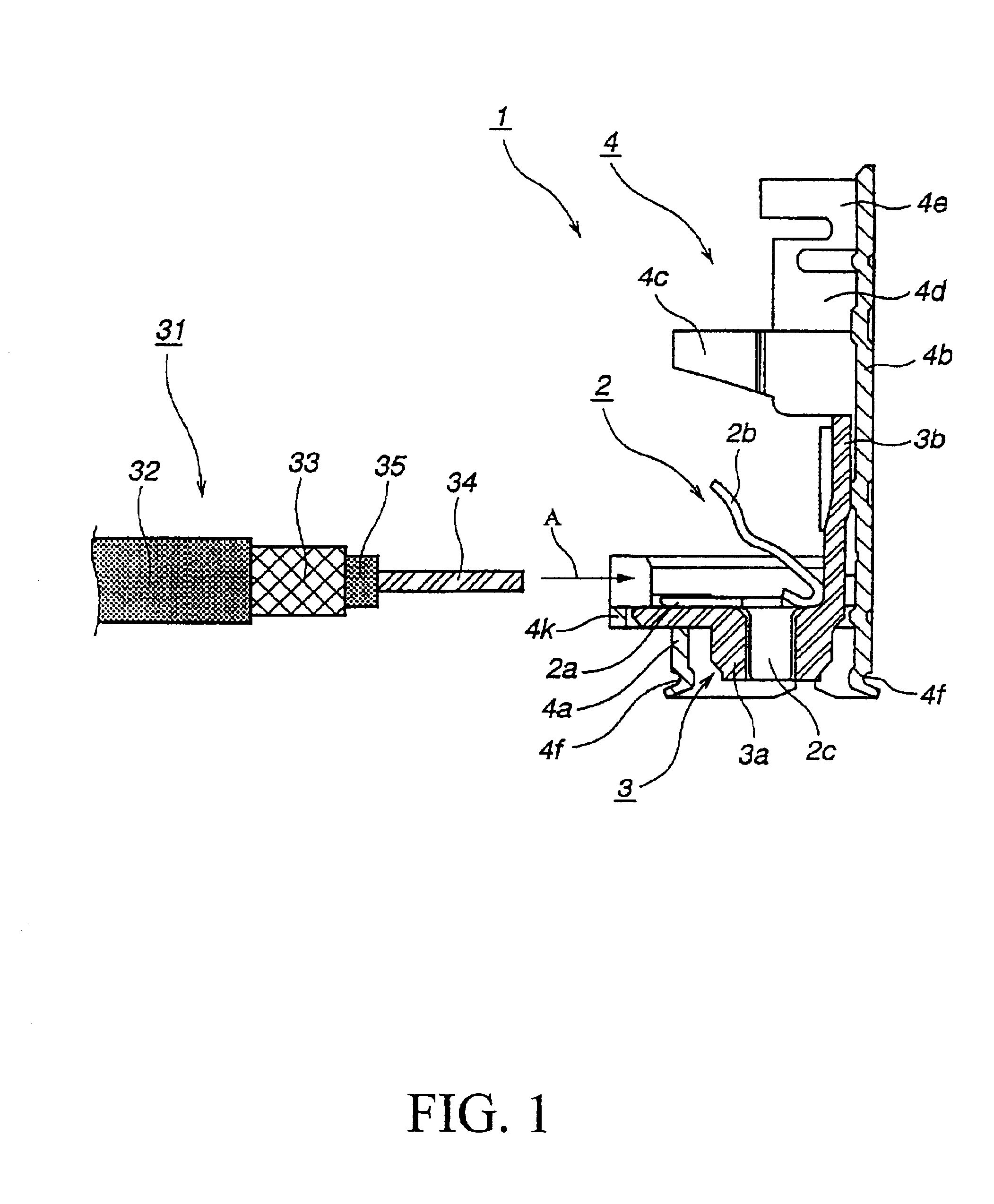
FIG. 1 is a schematic cross section of the relevant parts of the coaxial cable connector of an embodiment according to the present invention, and, in particular, is a diagram showing the state of the coaxial cable connector prior to the connection of the coaxial cable.

This coaxial cable connector (hereinafter simply referred to as "connector") 1, as shown in FIG. 1, comprises a connection terminal 2 to be connected to an internal conductor 34 of a coaxial cable 31, and a metal shell 4 for supporting the connection terminal 2 via an insulating member 3.

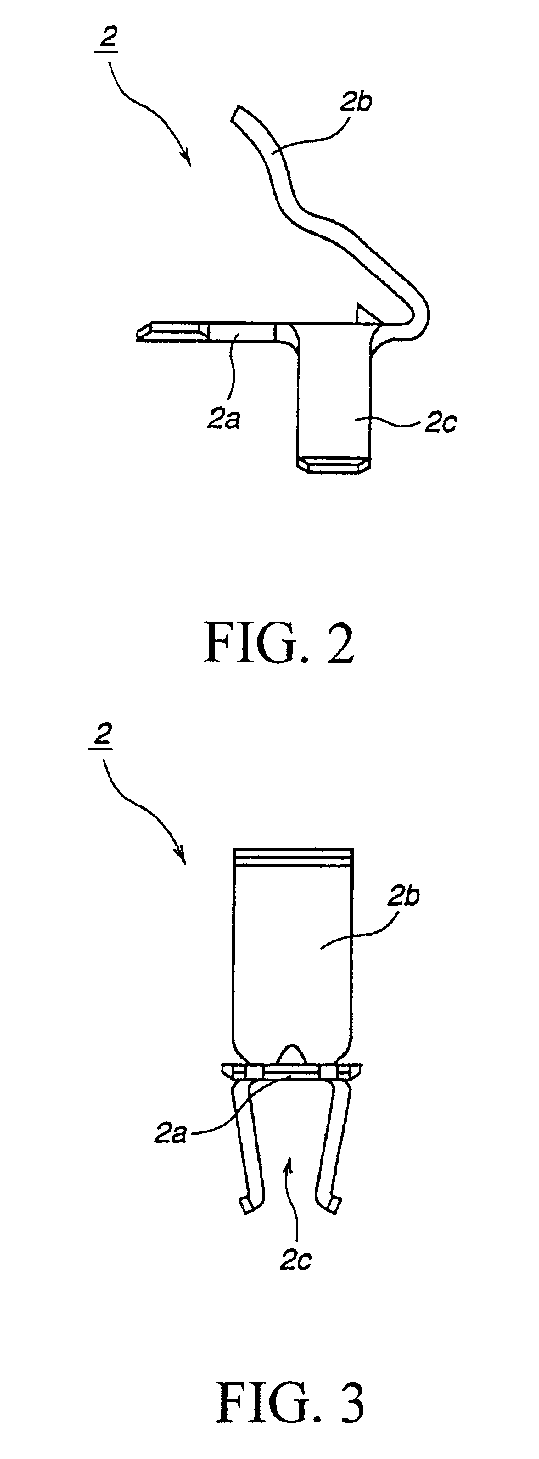
Among the above components, the connection terminal 2, as shown in in FIG. 2, which is an enlarged schematic front view of such connection terminal 2, is constituted by a pair of contacts 2a, 2b facing each other and formed by bending a metal blade spring into an approximate dogleg shape, and an engagement member ...


PUM


Abstract

A coaxial cable connector 1 including a connection terminal (2) to be connected to an internal conductor (34) of a coaxial cable 31 and a metal shell (4) for supporting the connection terminal (2) via an insulating member 3 establishes electrical connection between the internal conductor (34) of the coaxial cable (31) and the connection terminal (2) by bending the connection terminal (2) according to the respective bending forces of the shell (4) and the insulating member (3) and making such connection terminal (2) retain the internal conductor (34) of the coaxial cable (31).

Description

This application is based upon and claims the benefit of priority from the prior Japanese Patent Application No. 2001-129413 filed on Apr. 26, 2001; the entire contents of this prior application being incorporated herein by reference.1. Field of the InventionThe present invention relates to a cable-relay connector used in IT devices such as laptop computers and compact electronic devices such as home electric appliances, and particularly to a coaxial cable connector for connecting coaxial cables.2. Description of the Related ArtNumerous coaxial cables are used for the internal wiring of IT devices such as laptop computers and compact electronic devices such as home electric appliances, and such coaxial cables are usually used by being electrically connected to the respective conductors of other cables, substrates or the like.In order to electrically connect such coaxial cables to, for example, a conductor of another cables, conventionally, internal conductors of the respective coaxi...

Claims


Application Information

Patent Timeline
Patent Type & Authority Patents(United States)
IPC IPC(8): H01R9/05H01R4/18H01R4/10H01R103/00
CPCH01R9/0518H01R4/185
Inventor OBAYASHI, KATSUAKI
Owner DAIICHI SEIKO CO LTD
Learn More