
Prism diffuser for diffracting and spreading light

a diffuser and diffuser technology, applied in the direction of mountings, optics, instruments, etc., can solve the problems of reducing the transmission ratio of light, unclear transmission and reflected light,

Inactive Publication Date: 2004-09-28
CHEIL IND INC
View PDF16 Cites 94 Cited by
  • Summary
  • Abstract
  • Description
  • Claims
  • Application Information

AI Technical Summary

Benefits of technology

It is another object of the present invention to provide a prism diffuser for diffracting and spreading light which is capable of diffracting a transmitted and reflected light in a certain direction wherein a transmitted and reflected light is spread and concentrated in a diffracted region and is lighted up in a spread state.
It is still another object of the present invention to provide a prism diffuser for diffracting and spreading light which is capable of diffracting and spreading light in two directions or intensively diffracting in one direction for thereby transmitting or reflecting the light.
To achieve the above objects, there is provided a prism diffuser for diffracting and spreading light which includes a medium formed of a material capable of transmitting or reflecting light, a light diffracting member in which a plurality of fine protrusion surfaces of a micron unit are continuously connected on one surface of the medium, and the neighboring fine protrusion surfaces are formed in parallel in a certain direction for thereby diffracting light, and a light spreading protrusion member which is formed in a micron unit size greatly smaller than a width and height of the light diffracting member, and a plurality of the same are continuously formed in vertical and horizontal directions on the surface of the light diffracting member and is formed in a longitudinal shape and has a long diameter and a short diameter and has a certain surface curvature for thereby effectively spreading light.

Problems solved by technology

However, the above method decreases a transmission ratio of light, so that the transmitted and reflected light is unclear.

Method used


Image

  • Prism diffuser for diffracting and spreading light
  • Prism diffuser for diffracting and spreading light
  • Prism diffuser for diffracting and spreading light

Examples


Embodiment Construction

The preferred embodiments of the present invention will be explained with reference to the accompanying drawings.

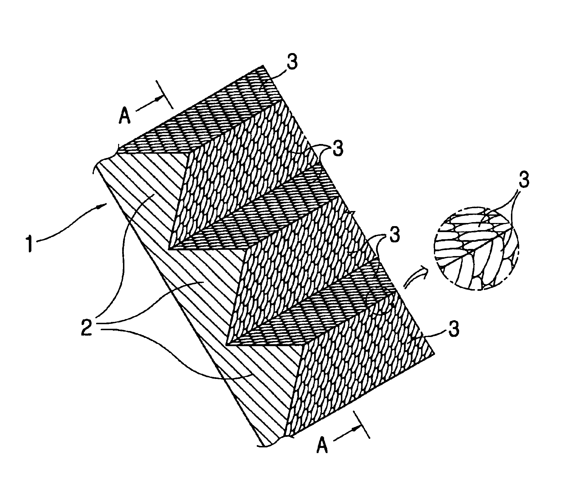
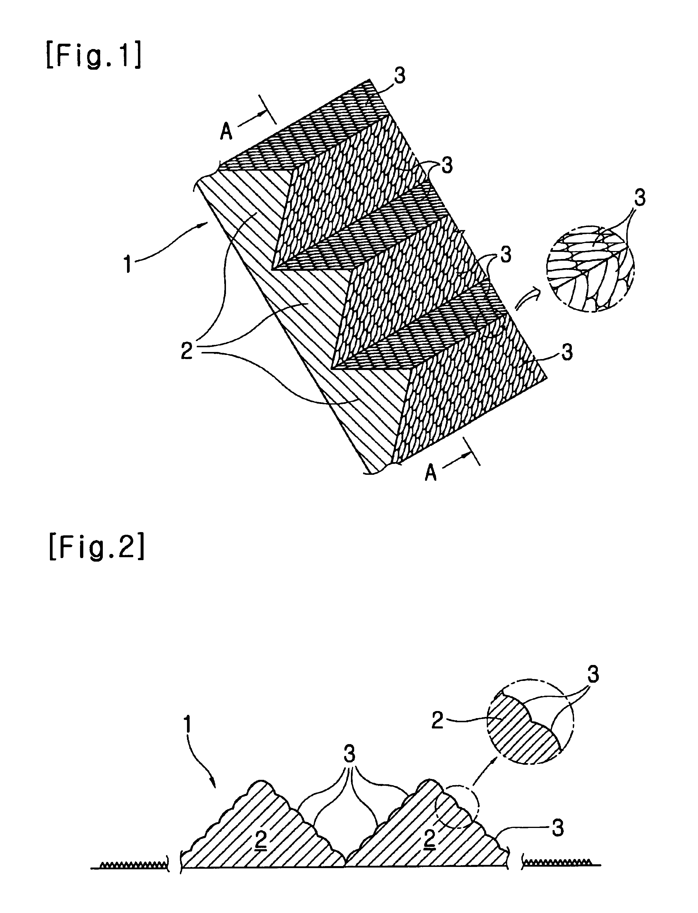
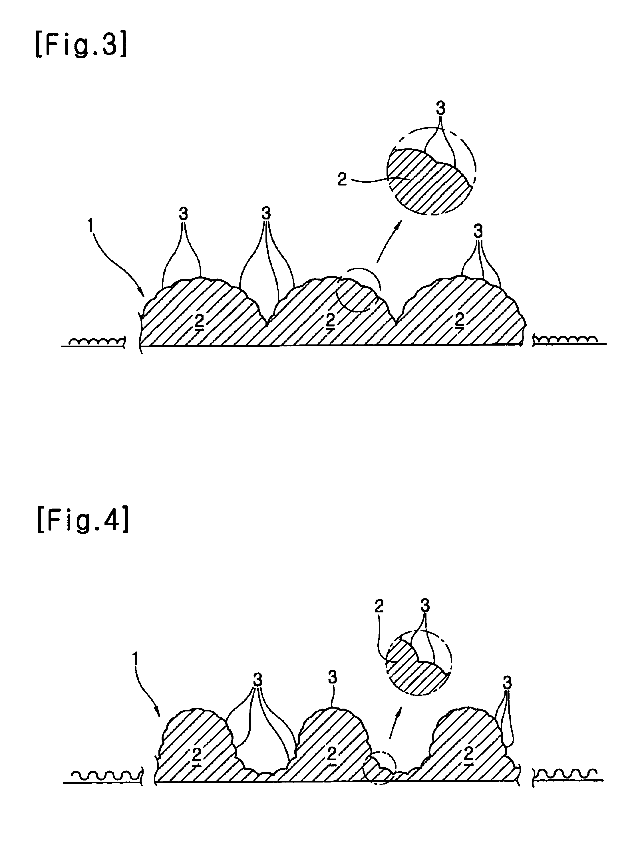
FIG. 1 is a partial enlarged perspective view illustrating a prism diffuser combined with a diffracting structure and a spreading structure according to an embodiment of the present invention, FIG. 2 is an enlarged cross-sectional view taken along line A--A according to the embodiment of FIG. 1, FIGS. 3 through 5 are views illustrating partial enlarged cross-sectional views illustrating other embodiments of the present invention, FIG. 6 is a partial enlarged perspective view illustrating a prism diffuser combined with a diffracting structure and a spreading structure according to another embodiment of the present invention, FIGS. 7A and B through FIGS. 12A and B are views illustrating a light transmission or diffraction and spreading state of light using a medium combined with a diffracting structure and a refracting structure according to the present invention and a ligh...


PUM

PropertyMeasurementUnit
diameteraaaaaaaaaa
widthaaaaaaaaaa
heightaaaaaaaaaa

Abstract

The present invention relates to a prism diffuser for diffracting and spreading light, and in particular to a prism diffuser for diffracting and spreading light which is capable of spreading light in a certain direction at a wider angle based on a structure combined with a prism capable of diffracting light on a surface of a medium formed of a glass which transmits or reflect light, a film formed of a transparent synthetic resin material or a metallic plate and a diffuser capable of spreading light and diffracting, spreading and transmitting light into two directions or diffracting, spreading and reflecting light in one direction.

Description

1. Technical FieldThe present invention relates to a prism diffuser for diffracting and spreading light, and in particular to a prism diffuser for diffracting and spreading light which is capable of spreading light in a certain direction(the light is spread in a wider elliptical direction and the light is narrowly spread in an orthogonal direction) at a wider angle based on a structure combined with a prism capable of diffracting light on a surface of a medium formed of a glass which transmits or reflect light, a film formed of a transparent synthetic resin material or a metallic plate and a diffuser capable of spreading light and diffracting, spreading and transmitting light into two directions or diffracting, spreading and reflecting light in one direction.2. Background ArtGenerally, since an object through which light transmits or an object which reflects light like a mirror has a small diffracting angle, the transmission and reflection range of light is narrow. In addition, as t...

Claims


Application Information

Patent Timeline
Patent Type & Authority Patents(United States)
IPC IPC(8): G02B5/04G02B5/02G02B5/18G02F1/13357
CPCG02B5/0231G02B5/0252G02B5/045G02B6/0038G02B6/0043G02B5/04
Inventor KIM, MAN-SUK
Owner CHEIL IND INC
Learn More