Kneepad assembly

a technology of knee pads and joints, applied in the field of knee pads, can solve the problems of knee pain and knee injury, and achieve the effect of preventing the injury of the knee join

Inactive Publication Date: 2004-10-26
SHIRCLIFF DAVID E
View PDF13 Cites 18 Cited by
  • Summary
  • Abstract
  • Description
  • Claims
  • Application Information

AI Technical Summary

Problems solved by technology

Many individuals who work installing tile, wood flooring, etc. have to spend a considerable amount of time on one or more knees in order to accomplish the work this can lead to knee pain as well as knee injury.

Method used


Image

  • Kneepad assembly
  • Kneepad assembly
  • Kneepad assembly

Examples


Embodiment Construction

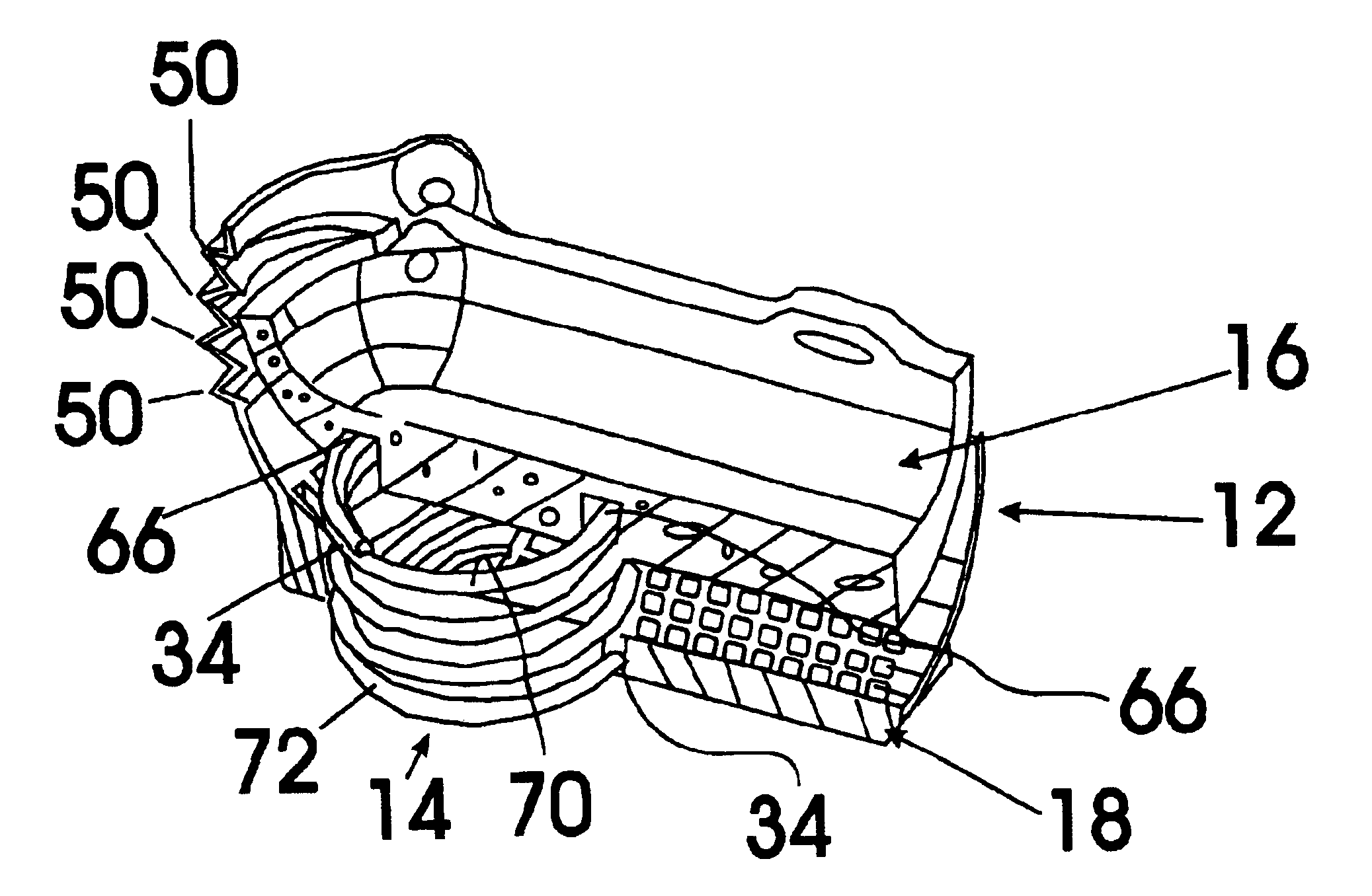
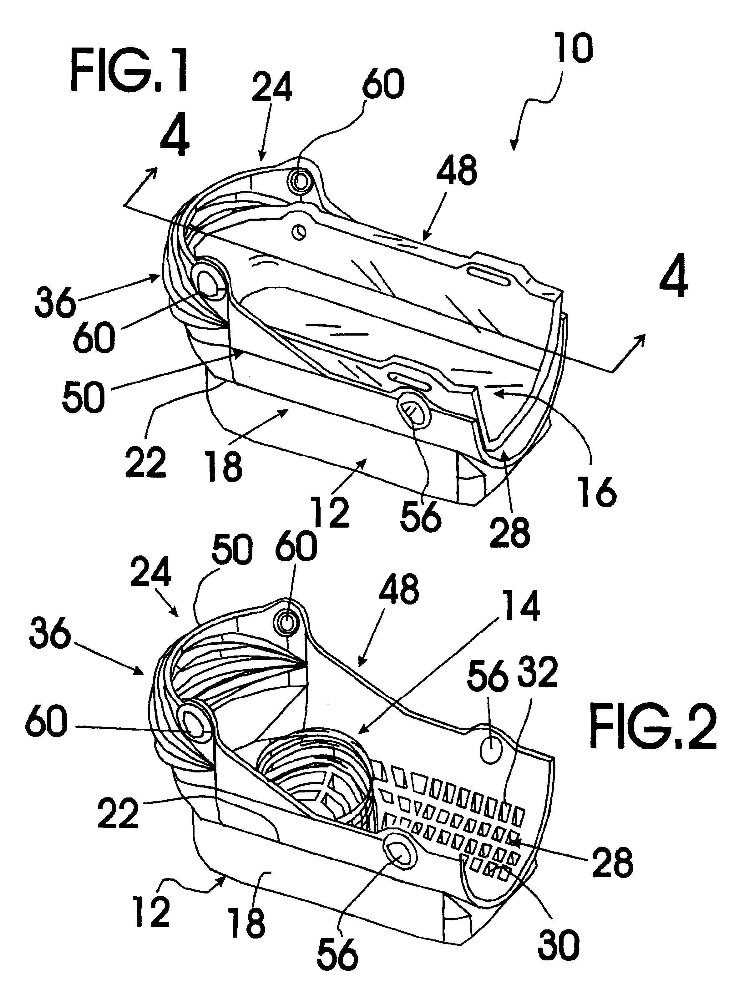
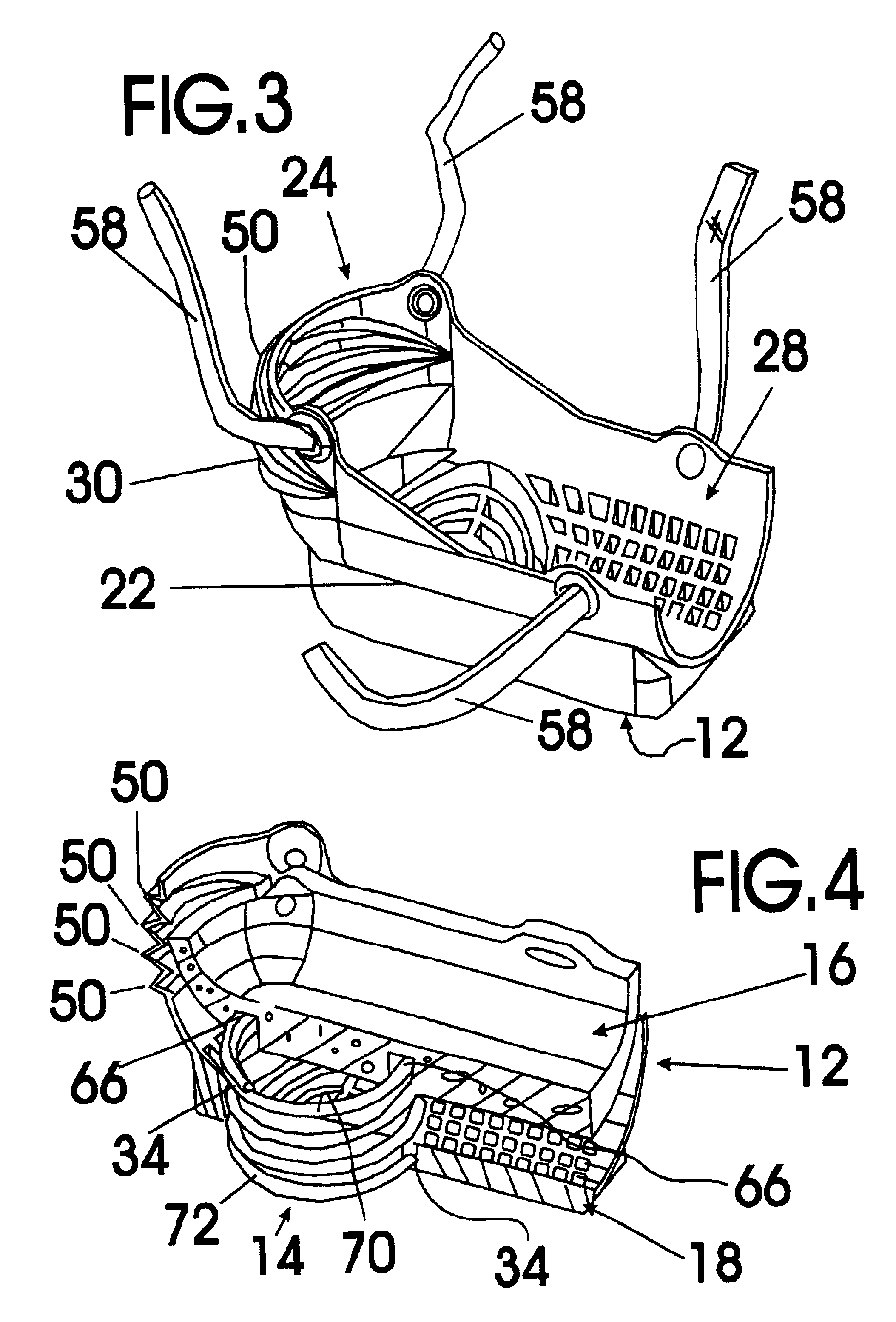
FIGS. 1-8 show various aspects of an exemplary embodiment of the kneepad assembly of the present invention generally designated 10. Kneepad assembly knee pad system 10 includes an outer knee pad structure, generally designated 12; a knee cap support spring, generally designated 14; and a resilient foam inner knee and shin pad structure, generally designated 16.

Outer knee pad structure 12 being molded of plastic and including a bottom knee support plate, generally designated 18, having a non-slip bottom surface 20 and a top portion 22 integrally formed with a knee and shin receiving structure, generally designated 24, that defines an inner knee and shin pad receiving channel 28. Inner knee and shin pad receiving channel 28 is partially defined by a bottom channel surface 30 of knee and shin receiving structure 24 that has a number of impact absorbing cavities 32 and a spring bottom receiving channel 34 provided therein. Inner knee and shin pad receiving channel 28 is also partially d...


PUM


Abstract

A knee pad assembly for protecting a knee of a worker installing tile, wood floors, etc. The knee pad assembly includes an outer knee pad structure, a knee cap support spring, and a resilient foam inner knee and shin pad structure.

Description

The present invention relates to workmen's equipment and more particularly to a knee pad assembly for protecting the knee of a worker that includes an outer knee pad structure, a knee cap support spring, and a resilient foam inner knee and shin pad structure; the outer knee pad structure being molded of plastic and including a bottom knee support plate having a non-slip bottom surface and a top portion integrally formed with a knee and shin receiving structure that defines an inner knee and shin pad receiving channel; the inner knee and shin pad receiving channel being partially defined by a bottom channel surface of the knee and shin receiving structure having a number of impact absorbing cavities and a spring bottom receiving channel; the inner knee and shin pad receiving channel being further partially defined by an accordion fold portion extending upwardly from a front end of the bottom channel surface; the inner knee and shin pad receiving channel being still further partially ...

Claims


Application Information

Patent Timeline
Patent Type & Authority Patents(United States)
IPC IPC(8): A41D13/06A41D13/05
CPCA41D13/065A41D13/0568
Inventor SHIRCLIFF, DAVID E.
Owner SHIRCLIFF DAVID E
Why Eureka
Try Eureka