Method and apparatus for removal of grease, smoke and odor from exhaust systems

a technology of exhaust system and grease, applied in the direction of lighting and heating equipment, domestic stoves or ranges, heating types, etc., can solve the problem of natural instability of ozon

Inactive Publication Date: 2004-11-16
GALLAGHER ARLEN W
View PDF24 Cites 22 Cited by
  • Summary
  • Abstract
  • Description
  • Claims
  • Application Information

AI Technical Summary

Benefits of technology

Another object of the present invention is to provide a ventilator apparatus which generates a sheet or film of water with entrained ozone which is suspended and recirculated by a flow of air, thereby efficiently and continuously removing contaminants by centrifugal force, entrapment, oxidation and condensation.
Another object of this invention is to provide a ventilator apparatus which discharges ozone into an exhaust stream thereby oxidizing contaminants and avoiding repeated cleaning of the apparatus.
In accordance with the present invention, there is provided an apparatus for extracting grease and other contaminants from an exhaust airstream in which a housing includes means for inducing the flow of exhaust airstream therethrough and, alternatively, water-injecting means are provided for injecting water into the housing in countercurrent relation to the flow of the exhaust airstream, the improvement comprising a source of ozone and discharge means for injecting the ozone continuously into the exhaust airstream prior to intermixture of the exhaust airstream with the water so as to create a vortex of ozonated water for efficient removal of the grease and other contaminants from the airstream.
In accomplishing the foregoing, an ozone-producing apparatus, or ozone generator, produces a concentration of pure ozone which is introduced into the exhaust air which is moving upwardly through an air inlet passage between an air inlet baffle and a back wall of a scrubbing chamber. Fresh water is introduced above the air inlet and by gravitation moved downwardly along the air inlet baffle where it slides off horizontally into the vertically upward path of the ozonated exhaust airstream. The ozonated exhaust air is intercepted by the flow of water moving horizontally away from the air inlet baffle, thereby lifting the water upwardly and through a narrow channel formed by the air inlet baffle and the back wall of the scrubbing chamber. The ozonated exhaust air combines with the water flow causing ozone to be entrained within the water flow. Ozone is naturally unstable and will oxidize and react with a target compound, such as, grease, odors and smoke, the ozone reverting to molecular oxygen as a byproduct. As the volume of water suspended in the ozonated exhaust airstream increases, the weight of the water against the upward air movement will cause its spread in a horizontal direction resulting in an even distribution of recirculated water throughout the entire length of the unit. When the weight of water suspended within the ozonated airstream reaches the maximum amount that can be supported, it is free to drain downwardly along the rear wall of the scrubbing chamber into a full width trough; and the excess water together with any entrained contaminants may then be suitably carried away through a conventional drain into the building drainage system.

Problems solved by technology

Although the system of the '457 patent has proven highly effective in use, it does require some maintenance and cleaning on a regular basis as contaminants collect and accumulate on the interior walls of the ventilator.
Ozone is naturally unstable and will oxidize and react with a target compound, such as, grease, odors and smoke, the ozone reverting to molecular oxygen as a byproduct.

Method used


Image

  • Method and apparatus for removal of grease, smoke and odor from exhaust systems
  • Method and apparatus for removal of grease, smoke and odor from exhaust systems
  • Method and apparatus for removal of grease, smoke and odor from exhaust systems

Examples


Embodiment Construction

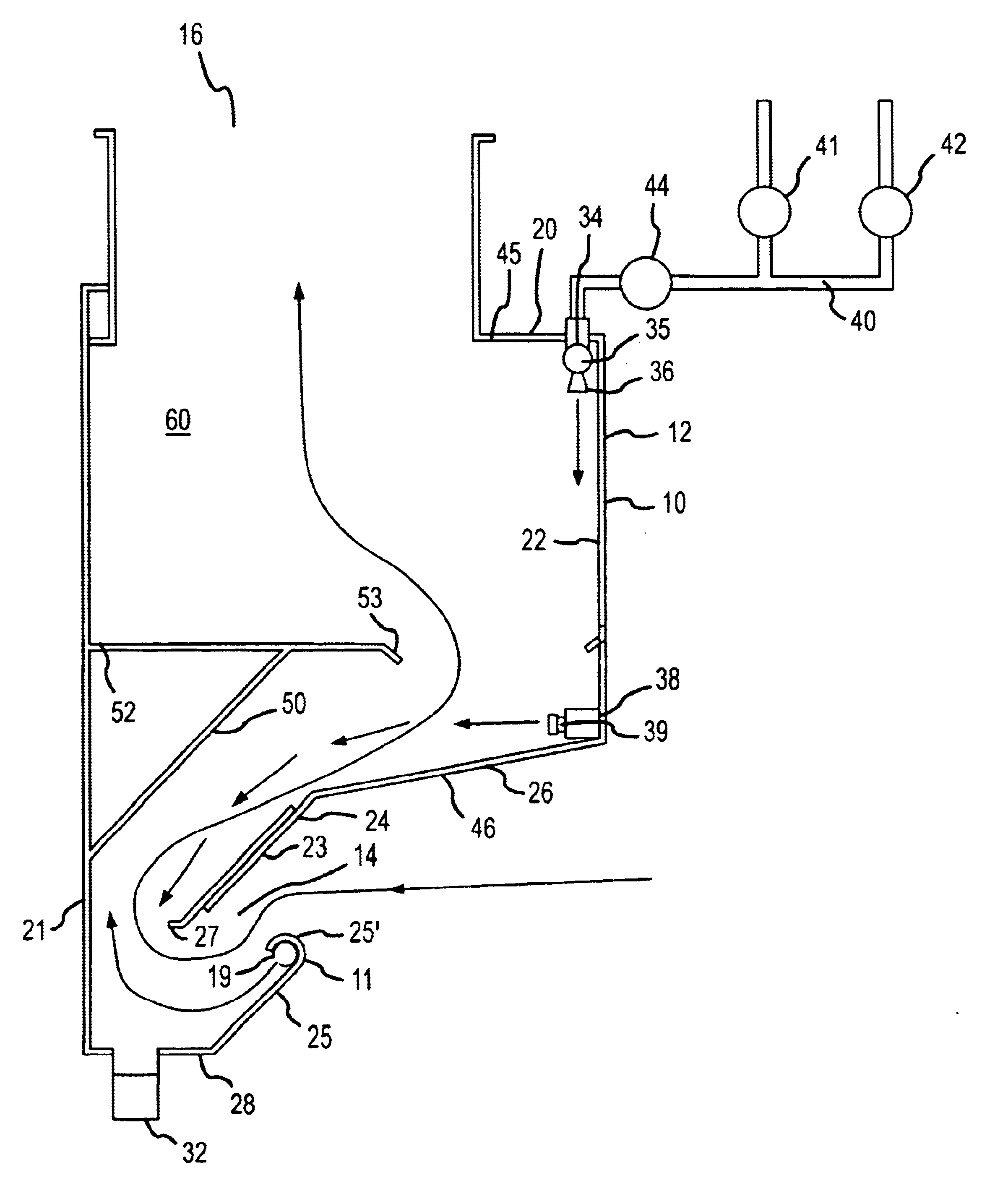
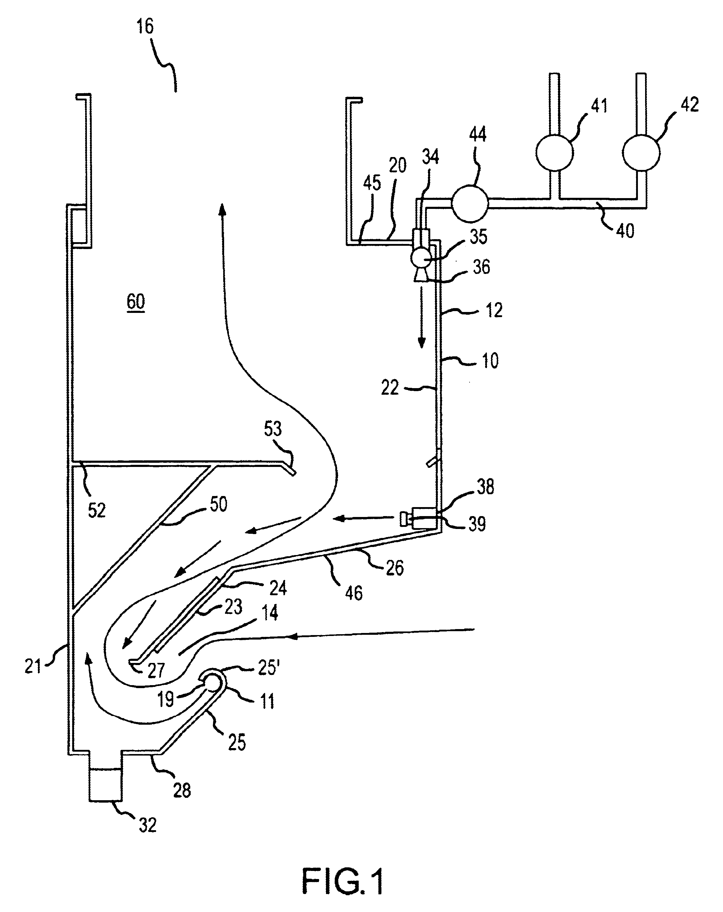
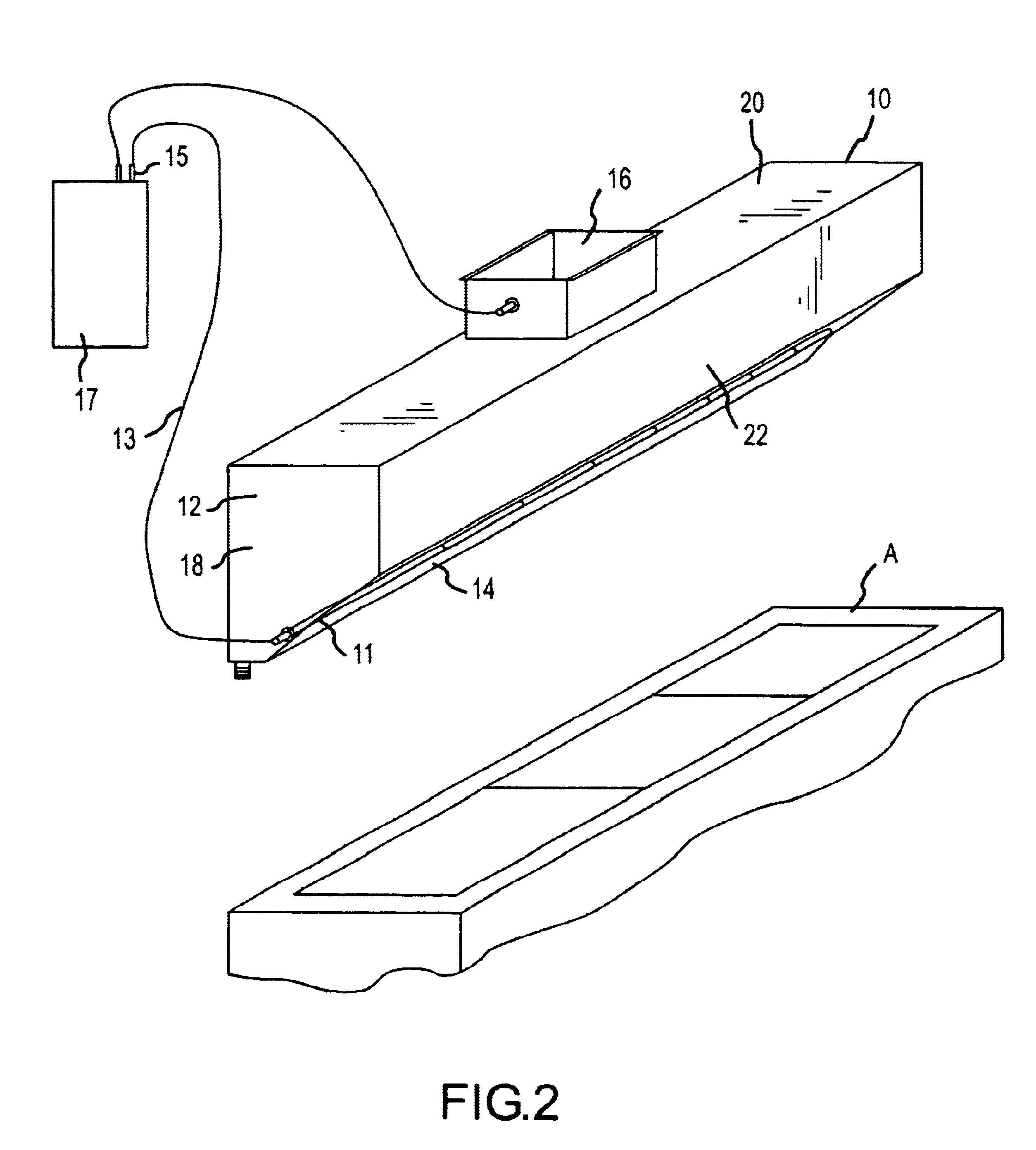
Referring in more detail to the drawings, specifically FIGS. 1 and 2, a preferred form of ventilator apparatus 10 is installed in a conventional manner above a cooking appliance A and is made up broadly of a hood or housing 12 having a lower inlet passage area 14 and an upper exhaust duct 16. In a well-known manner, the exhaust duct or collar 16 is connected into the flue of a chimney or other exhaust system available in the building, which typically includes an exhaust fan downstream of the exhaust duct 16, to induce the upward and outward flow of vapors and contaminants generated by the cooking appliance through the air inlet passage 14.

In the preferred form, the hood 12 is of generally rectangular configuration and elongated to traverse the substantial width of the cooking appliance and with the air inlet passage centered in spaced relation above the appliance. As further shown in FIGS. 1 and 2, the exterior of the hood 12 includes opposite end walls 18, a top horizontal wall 20 ...


PUM


Abstract

A grease, smoke, and odor extraction system includes an outer housing including a lower entrance passage and an upper exit duct for drawing the exhaust airstream upwardly through a scrubbing chamber, the lower entrance passage is fitted with a pipe which discharges ozone gas into the exhaust air and, alternatively, a water supply manifold which directs the water into the ozonated exhaust stream at the chamber area in such as way as to create a vortex of water droplets in the ozonated exhaust stream to encourage the extraction of grease, fumes, and other contaminants from the stream. Several alternate embodiments as described including a housing, an ozone generator, an ozone injector into the housing in combination with a baffle member and alternatively water and filter members for use with kitchen exhaust systems as well as water treatment systems and the like.

Description

BACKGROUND AND FIELD OF INVENTIONThis invention is directed to improvements in ventilating systems of the type disclosed in U.S. Pat. No. 5,042,457 ('457) for GREASE EXTRACTION VENTILATOR APPARATUS, by Arlen W. Gallagher, owned by the inventor of this invention. One purpose of the '457 patent was to provide a ventilator system in which the grease vapors and lint could be removed without a water reservoir or grease entrapment area at the bottom, as well as to avoid accumulation on the interior walls of the ventilator and particularly to avoid baked-on grease deposits which will prevent water from absorbing heat from the walls of the ventilator. Although the system of the '457 patent has proven highly effective in use, it does require some maintenance and cleaning on a regular basis as contaminants collect and accumulate on the interior walls of the ventilator.It is desirable to provide a ventilator system in which contaminants, including odors, can be removed through use of ozone in ...

Claims


Application Information

Patent Timeline
Patent Type & Authority Patents(United States)
IPC IPC(8): F24C15/20
CPCF24C15/20
Inventor GALLAGHER, ARLEN W.
Owner GALLAGHER ARLEN W
Why Eureka
Try Eureka