Container diverter

a container and divider technology, applied in the field of containers, can solve the problems of bottle label misalignment or even total missing, bottle bottle label may not be properly aligned or positioned, and the bottle bottle may be commercially unacceptable. , to achieve the effect of smooth removal of the articl

Inactive Publication Date: 2004-11-23
LABATT BREWING CO LTD
View PDF30 Cites 17 Cited by
  • Summary
  • Abstract
  • Description
  • Claims
  • Application Information

AI Technical Summary

Benefits of technology

(ii) Can readily and easily be programmed to rotate a desired amount and
(iii) Return to its original or base position extremely rapidly.
However, in many operations and the bottle example referred to above is one, a lubricant is used to reduce the friction between the bottle base and the conveyor surface and assist the bottle slide. This appears to function adequately once the bottle starts to slide.
It will be appreciated that the orientation of the paddle in this preferred embodiment also takes into account tendencies of modern beverage bottles, especially beer bottles, to have a cylindrical body whose wall slopes slightly inward from the lower portion above the base to the shoulder area. In addition, the area immediately above the base extends radially further outwardly than the remainder of the main body area to provide a "bumper" zone. If adjacent bottles do contact each other it is via the bumper zone which prevents the upper cylindrical body areas from contacting. Since the body labels are usually carried by such areas, scuffing of the labels is also prevented or reduced.

Problems solved by technology

Obviously, in an operation involving so many bottles processed at those rates, there are going to be a number of bottles which are commercially unacceptable for various reasons.
For example, a bottle may be under-filled, or over-filled, with beer or the bottle label may be mis-aligned or even totally missing.
Such bottles are not acceptable and must be separated from the acceptable bottles prior to the latter proceeding to a packaging station.
This clearly complicates the removal of each unacceptable bottle since it must be removed without affecting the speed or direction of movement of the two adjacent and acceptable bottles and the effect the latter bottles may have on bottles adjacent to them and so on.
In another case a bottle with the label missing could result in the rejected bottle being returned to the labeller.
A number of disadvantages are associated with this type of device.
The use of a fluid, air in the case of a pneumatic activator, can be inconvenient and even cause problems not the least being the constant need to make adjustments to it for various reasons.
For example, fluctuations and especially reduction in, or loss of, pressure can result if the device has to operate virtually continuously for an extended period and the air pressure becomes inadequate to sustain the desired piston rejecter stroke.
Such extended use situations can happen if the bottle filler is incorrectly adjusted and a large number of low-fills are produced.
Another significant problem is that the pad is relatively narrow and, to be effective, must contact the moving bottle at virtually the longitudinal axis of the bottle to effect a clean redirect.
It will be appreciated that with all the variables in this system fine tuning even to maintain a centre of bottle hit is a constant issue.
Consequently, as can happen, the actuator is unavoidably triggered early or late, then the pad contacts the bottle off-centre possibly at the leading or trailing edge of the bottle and can cause same to spin or otherwise become unstable which, in combination with the "pull" from the conveyor, can result in toppling, hitting an adjacent bottle; etc.
If the actuator cycle is not fully completed in time, the next bottle will strike a part of the actuator assembly blocking the conveyor and this would definitely adversely disrupt the flow of bottles probably requiring the conveyor to be stopped.
In fact, the mode of action can result in cleanly rejected bottles being thrown over and cause significant problems downstream even if the bottles do manage to exit and remain outside of the path of the line of accepted bottles.
It does not, of course address other problems associated with this type of divertor.
It also requires relatively complex and expensive equipment to detect the lateral position of the bottles on the conveyor.
This, however, introduces its own problems with respect to increased wear etc. loss of controlled contact with the bottle thus requiring relatively frequent maintenance.
In any event, all these fluid-based systems are subject to certain inherent or built-in delays in their operation in view of the several mechanical etc. steps in the system which steps need to be completed from the time the signal to reject is received by the device to the time the bottle contacting bopper is returned to its base position.
However some of these devices, refer for example to that described in U.S. Pat. No. 3,471,012 use selective activation of the article pusher members and this involves a substantial time factor.
This device is extremely expensive and complex involving high maintenance and physically significant floor space.

Method used


Image

  • Container diverter
  • Container diverter
  • Container diverter

Examples


Embodiment Construction

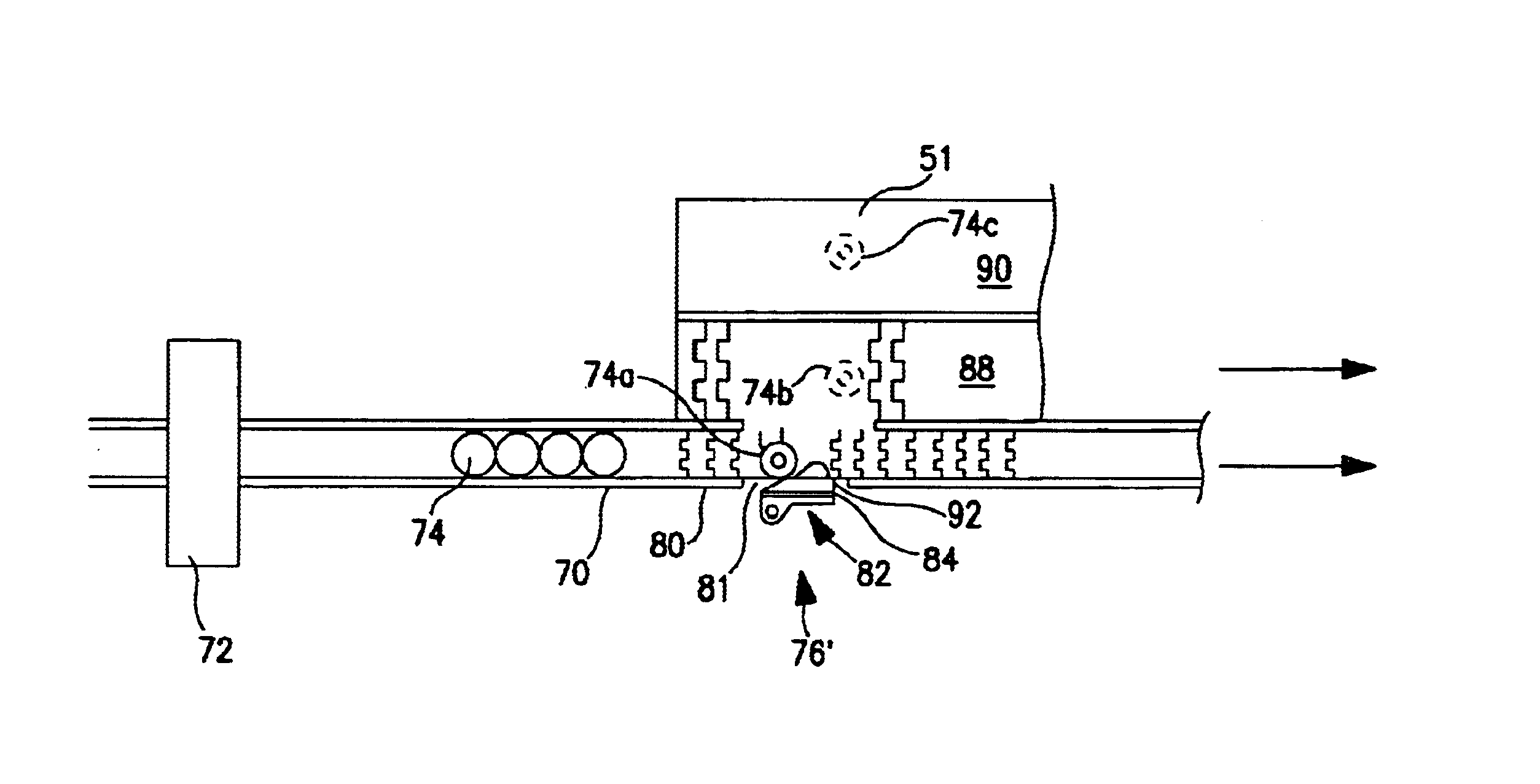
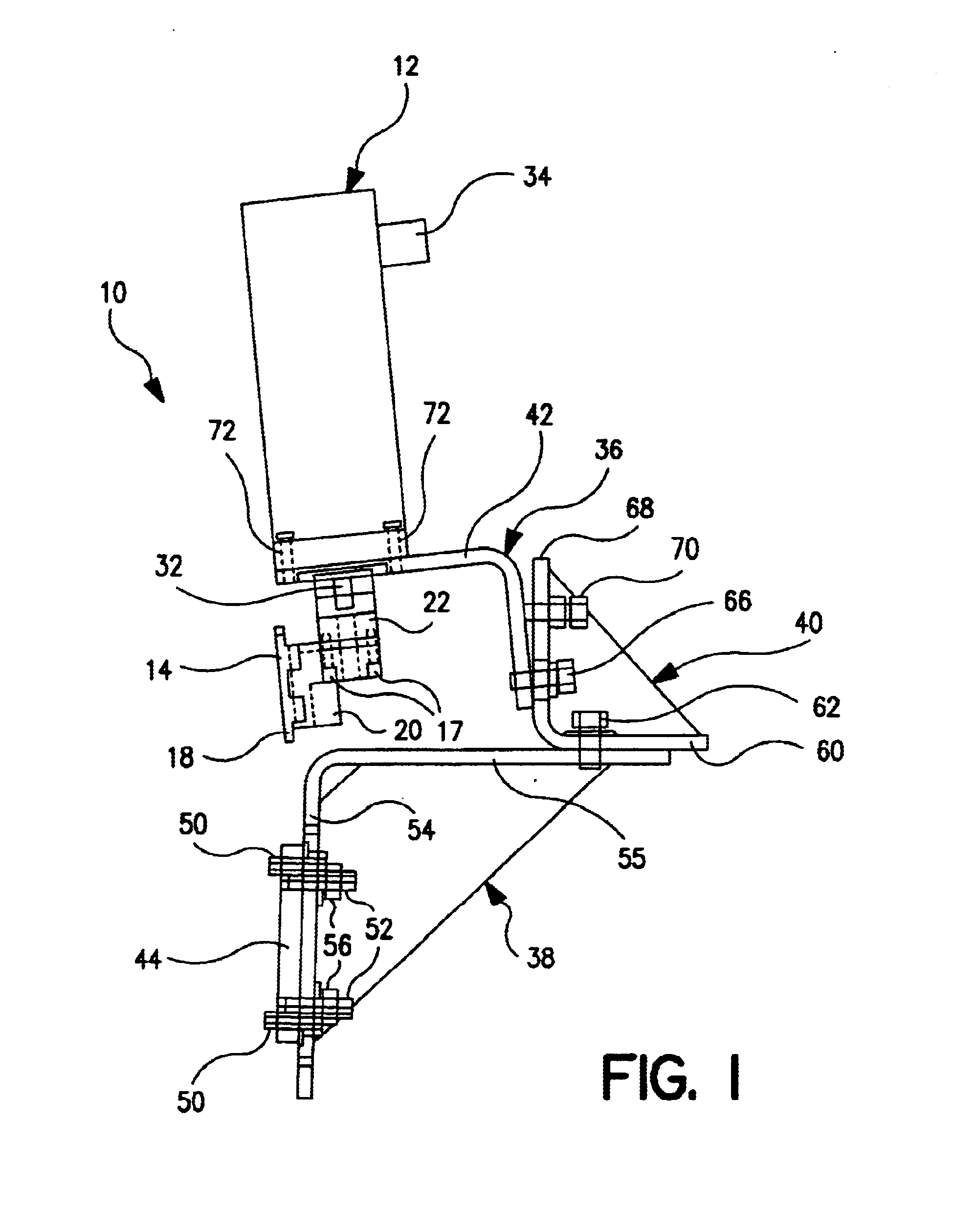
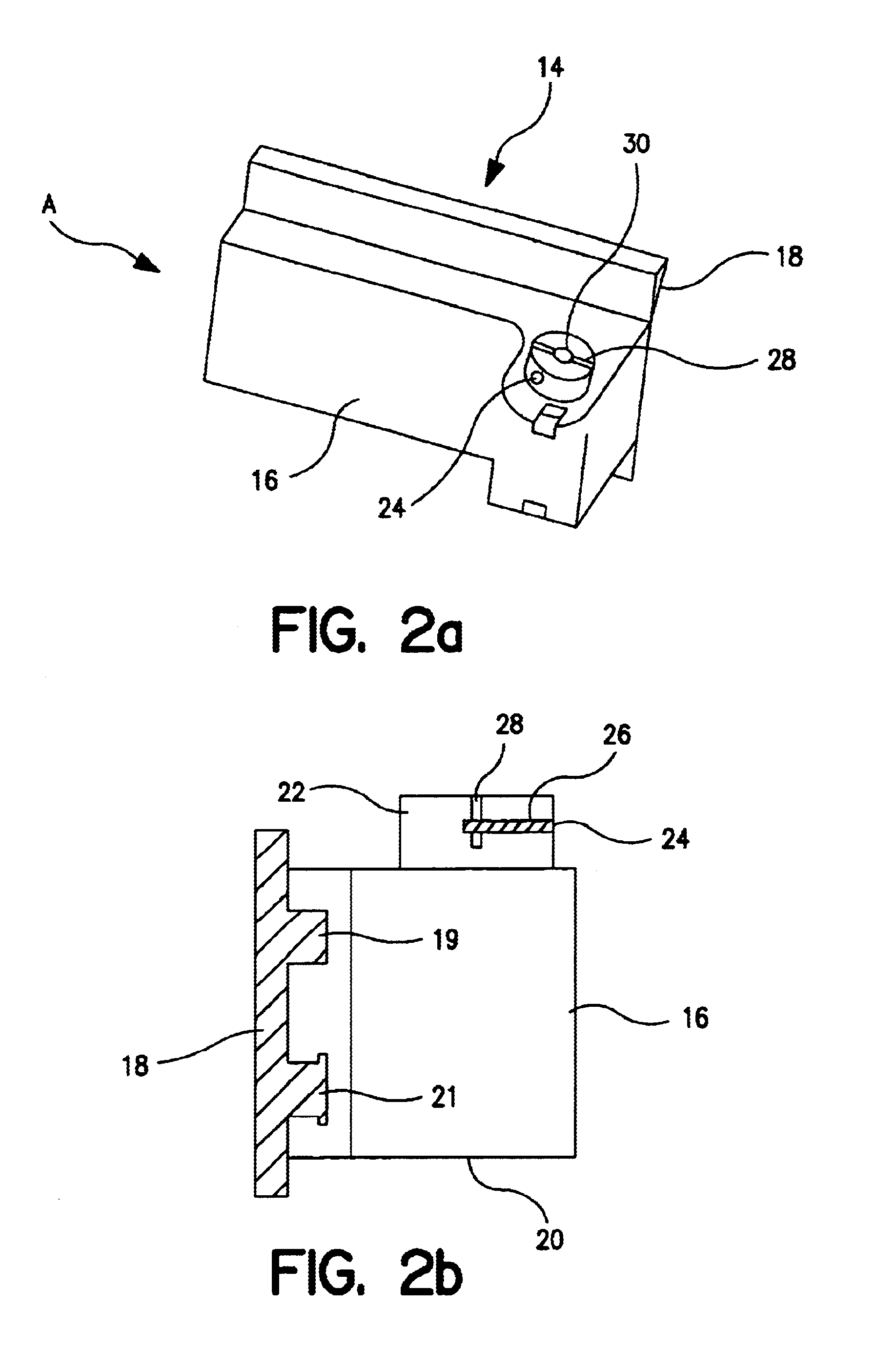
In one embodiment, the present invention provides: a method for diverting articles selected for removal from a stream of articles travelling along a pathway on a conveyor, said method comprising the steps of: locating adjacent said pathway a deflector member adapted to rotate into said pathway to contact and controllably sweep selected articles from said stream of articles; following removal of each selected article from said stream, reversing the rotation of said deflector member thereby removing same out of said pathway to allow subsequent non-selected articles in said stream to continue along said pathway without being impeded by said deflector member; and said deflector member being rotated by a synchronous motor acting in response to a predetermined signal to cause the said rotations of said deflector member.

In another embodiment the present invention provides: a device for diverting an article selected for removal from a stream of articles travelling along a pathway on a conve...


PUM


Abstract

The present invention provides a device and method for selectively removing an article from a stream or line of similar articles travelling in a pathway on a transport system such as a conveyor. The invention utilizes a synchronous electric motor which, in response to a signal to reject a specific article in the stream, rotates an article-contacting member or paddle into the path of the stream of articles travelling along the pathway whereby it contacts and smoothly removes that article from the stream. The use of a synchronous motor to effect the rotation of the paddle is very important to the present invention.

Description

1. Field of the InventionThe present invention relates to the handling of articles, such as beverage containers moving at high speed in modern production facilities. Of special interest is the use of the invention in the food and beverage industry and in particular the handling of bottles and cans containing alcoholic and non-alcoholic beverages. Examples of such beverages include beer and beer-based drinks such as shandies; coolers and low or non-alcoholic beers; non-alcoholic soft drinks such as colas; water; fruit juices and the like.2. Description of Prior ArtIn many industries and, in particular, the beverage industry, product units such as bottles and cans are often transported in production facilities in lines or streams at high speed using conveyor systems. In some instances, the pathway defined by the conveyor is not much wider than the moving container but is sufficient to allow for free movement of the container along the conveyor. The conveyor is set up such that the con...

Claims


Application Information

Patent Timeline
Patent Type & Authority Patents(United States)
IPC IPC(8): B65G47/82B65G47/74B65G47/76
CPCB07C5/3408B65G47/82B65G47/766B65G2201/0244
Inventor LINTON, FREDRICK L.
Owner LABATT BREWING CO LTD
Why Eureka
Try Eureka