

Wiper blade for cleaning glass surfaces on vehicles, especially motor vehicles
- Summary
- Abstract
- Description
- Claims
- Application Information
AI Technical Summary
Benefits of technology
Problems solved by technology
Method used
Image

Examples
Embodiment Construction
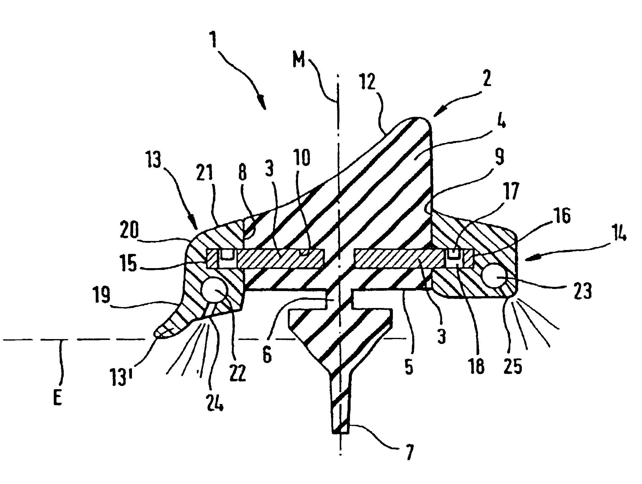
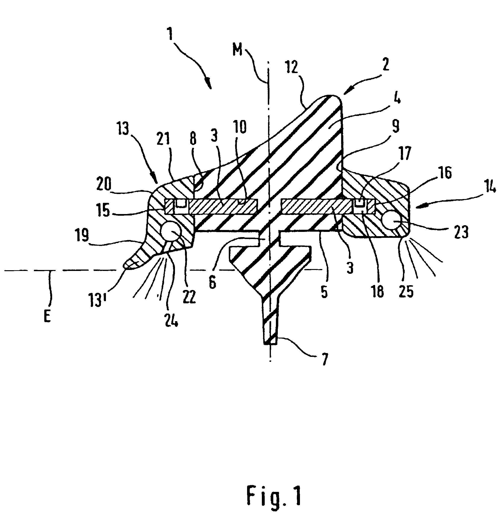
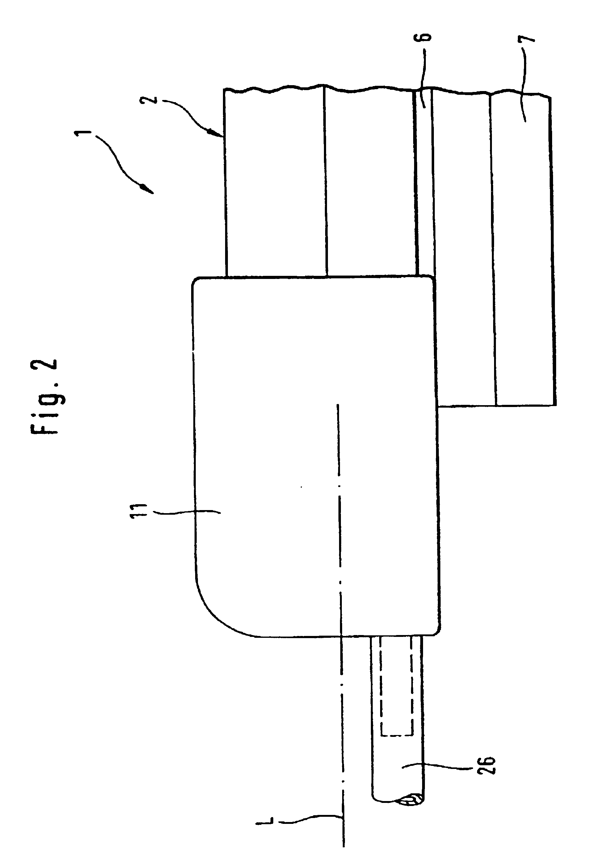
The wiper blade 1 shown in FIGS. 1 and 2 consists of a basically familiar wiper blade body 2 which is manufactured as an airfoil from a flexible rubber material, and from two ribbon-shaped support or spring splines 3 holding the wiper blade body 2 therebetween, which are manufactured from a flexible material, preferably from spring steel and which, like the wiper blade body 2, extend along the entire length of the wiper blade 1, which in FIG. 1 runs perpendicular to the drawing plane.
The cross-section of the wiper blade body 2 forms a section profile 4 with an underside 5 furnished by means of a flexible hinge 6 with the similarly formed-on lip 7, with which in the particular application the wiper blade 1 lies against the vehicle glass surface to be cleaned. A flexible hinge 6 and a lip 7 similarly extend along the entire length of the wiper blade body 2. In the embodiment shown the flexible hinge 6 is formed approximately in the middle of the underside 5, specifically in center pla...
PUM
 Abstract
Description
Claims
Application Information