Flash suppressor apparatus and methods

Inactive Publication Date: 2005-01-04
J & K IP ASSETS
View PDF24 Cites 55 Cited by
  • Summary
  • Abstract
  • Description
  • Claims
  • Application Information

AI Technical Summary

Problems solved by technology

In battle, muzzle blast may have serious adverse consequences.
It is also known that for certain sighting systems, muzzle blast from a gun may adversely impact the gun's own sighting system.
For example, some conventional devices are not fully effectiv

Method used


Image

  • Flash suppressor apparatus and methods
  • Flash suppressor apparatus and methods
  • Flash suppressor apparatus and methods

Examples


Embodiment Construction

The present invention is directed toward flash suppressor apparatus and methods, and more specifically, to flash suppressors having novel expansion features. Many specific details of certain embodiments of the invention are set forth in the following description and in FIGS. 1-7 to provide a thorough understanding of such embodiments. One skilled in the art, however, will understand that the present invention may have additional embodiments, or that the invention may be practiced without several of the details described in the following description.

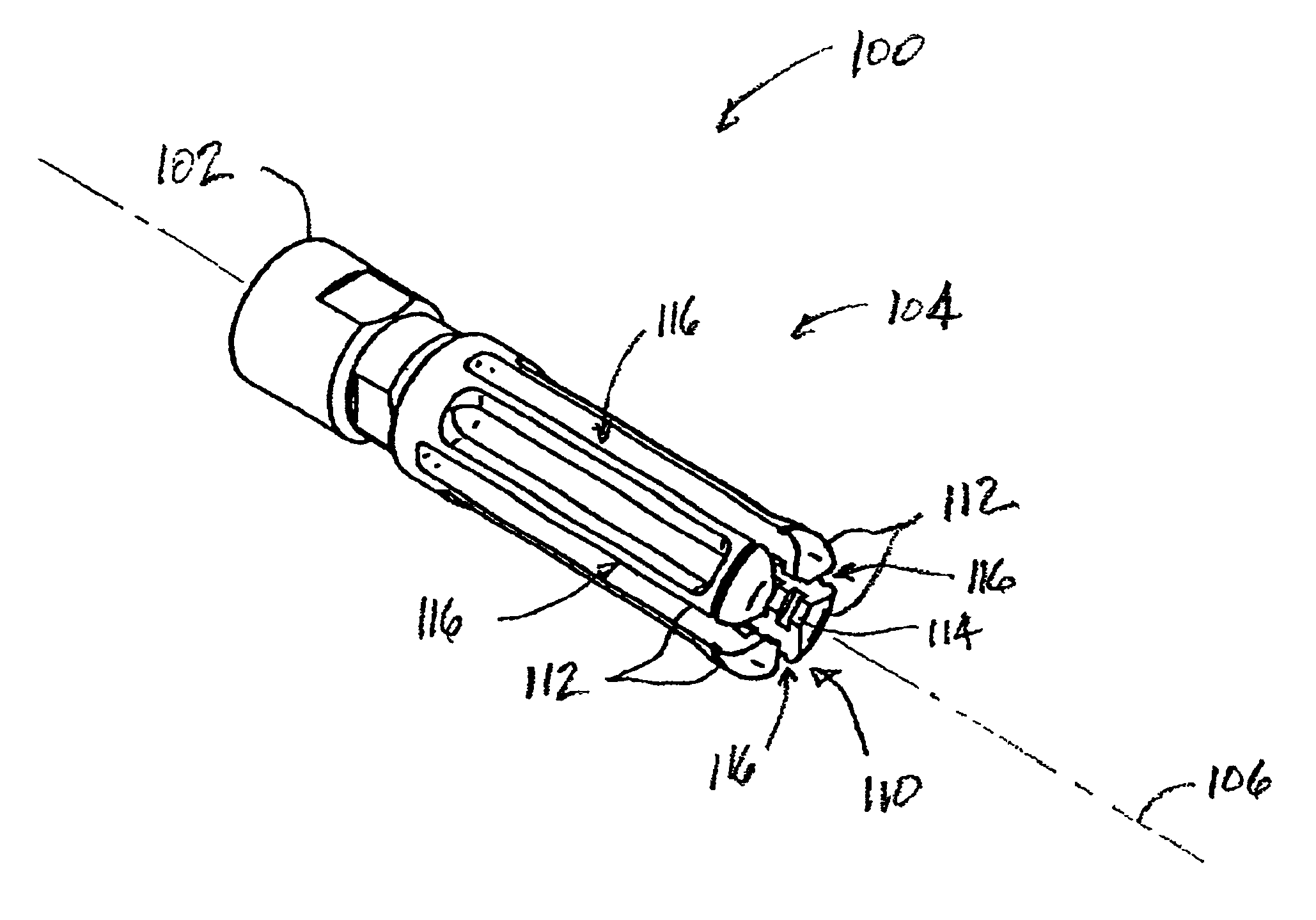
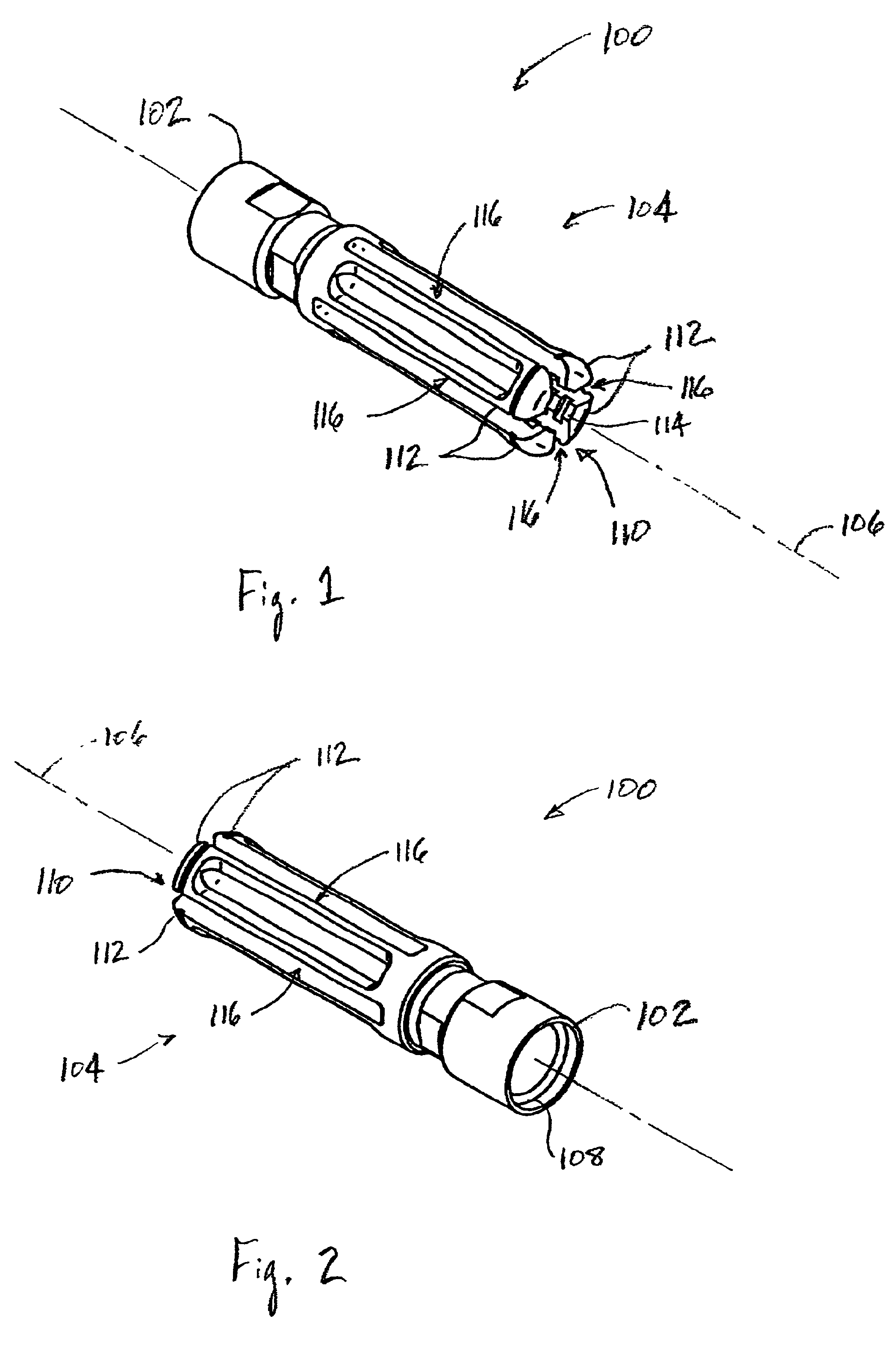
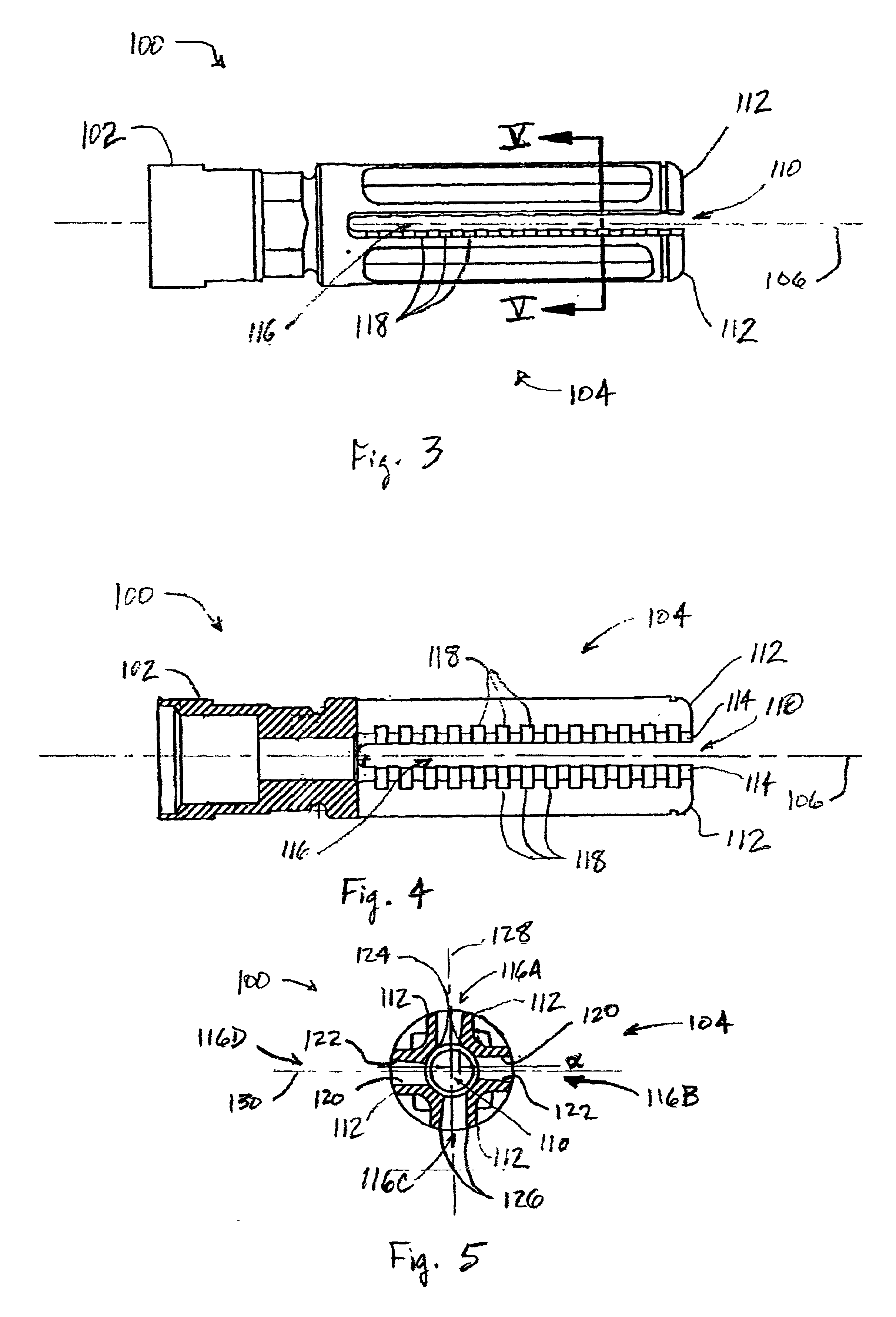
FIG. 1 is a front isometric view of a suppressor 100 in accordance with an embodiment of the invention. FIG. 2 is a rear isometric view of the suppressor 100 of FIG. 1. In the embodiment shown in FIGS. 1 and 2, the suppressor 100 includes an attachment portion 102 that is adapted to attach to a muzzle of a gun barrel (not shown), and a suppressor portion 104 that extends outwardly beyond the end of the gun barrel along a longitudinal axis...


PUM


Abstract

Flash suppressors having novel expansion features are disclosed. In one embodiment, a suppressor apparatus includes an attachment portion adapted to attach to a gun barrel, and a suppressor portion coupled to the attachment portion. The suppressor portion has a suppressor bore therethrough that is adapted to be aligned with a longitudinal axis of the gun barrel to allow a projectile from the gun barrel to pass therethrough. The suppressor bore is defined by at least one bore surface having at least one expansion groove disposed therein. The expansion groove may be partially-circumferentially disposed about the suppressor bore, or may include a plurality of expansion grooves. In another embodiment, a flash apparatus includes a suppressor portion having a plurality of longitudinally elongated members spaced apart about a circumference of the suppressor bore, each elongated member being separated from adjacent elongated members by a longitudinal slot, at least one longitudinal slot having non-parallel sidewalls.

Description

TECHNICAL FIELDThe present invention is directed toward flash suppressors, and more specifically, to flash suppressors having novel expansion features.BACKGROUND OF THE INVENTIONThe eruption of hot, high pressure gases from a gun barrel when a gun is fired is commonly referred to as muzzle blast. Muzzle blast is typically composed of an inner core of hot gases and partially burned particulate matter (e.g. unburned powder) emanating along a longitudinal axis extending out from the muzzle of the gun barrel. As a projectile exits from the muzzle, the hot gases rapidly expand outwardly into the surrounding air, mixing with the surrounding air and forming an oblique shock structure known as a “shock bottle.” The unburned particulate may ignite upon mixing with the oxygen-rich surrounding air. The result is that the inner core of hot gases and the burning particulate within the shock bottle produces a bright flash of light in both the visible and infrared portions of the spectrum.In battl...

Claims


Application Information

Patent Timeline
IPC IPC(8): F41A21/34F41A21/00
CPCF41A21/34
Inventor MEYERS, BRAD E.
Owner J & K IP ASSETS
Why Eureka
Try Eureka