Propelling charge increment protector for 120mm mortar ammunition

a technology for propelling charge increments and mortar ammunition, which is applied in the field of mortar shells, can solve the problems of warpage, increment protectors of mortar shells, and the need for matching halves

Inactive Publication Date: 2005-01-04
UNITED STATES OF AMERICA THE AS REPRESENTED BY THE SEC OF THE ARMY
View PDF15 Cites 11 Cited by
  • Summary
  • Abstract
  • Description
  • Claims
  • Application Information

AI Technical Summary

Problems solved by technology

Some disadvantages of the two-piece clam shell increment

Method used


Image

  • Propelling charge increment protector for 120mm mortar ammunition
  • Propelling charge increment protector for 120mm mortar ammunition
  • Propelling charge increment protector for 120mm mortar ammunition

Examples


Embodiment Construction

The invention is a propelling charge increment protector for a mortar shell, for example, a 120 mm mortar shell. The protector includes an injection-molded plastic part preferably made of a polycarbonate / acrylonitrile butydiene styrene (PC / ABS) plastic alloy and a foam insert made of polyethylene foam. The protector has many features that serve to protect the propelling charge increments, which are affixed to mortar shells during shipping, handling and firing.

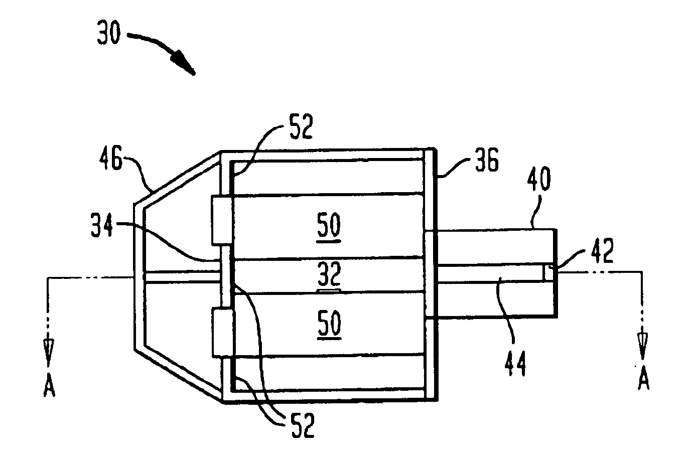
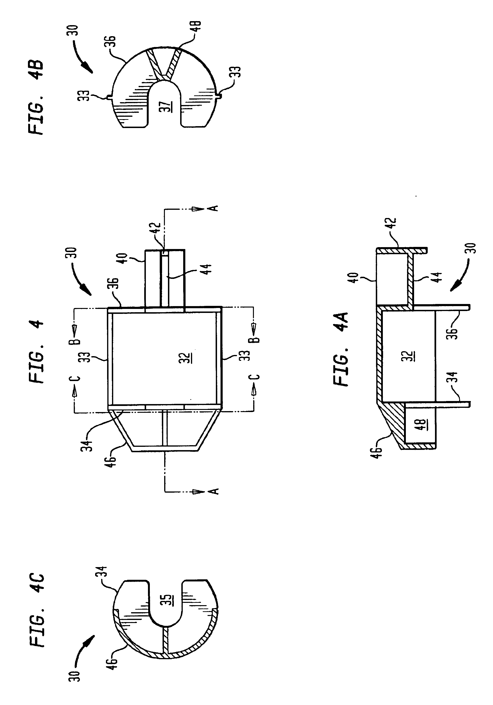
FIG. 4 is a bottom view of an increment protector 30 according to the invention. FIG. 4A is a sectional view along the line A—A of FIG. 4. FIG. 4B is a sectional view along the line B—B of FIG. 4. FIG. 4C is a sectional view along the line C—C of FIG. 4. Protector 30 includes a semi-cylindrical body 32 and front and rear generally horseshoe shaped end plates 34, 36 attached to the front and rear of the semi-cylindrical body, respectively. The end plates 34, 36 define openings 35, 37 therein. A wedge-shaped boom 40 is attached t...


PUM


Abstract

A protector for propelling charge increments on a mortar shell includes a semi-cylindrical body, the semi-cylindrical body arranged around a bottom and sides of the charge increments; two generally horseshoe shaped end plates attached to a front and a rear of the semi-cylindrical body, the end plates defining openings therein, the tail tube of the mortar fitting in the opening in each end plate, the charge increments being disposed between the two end plates; a wedge-shaped boom attached to the rear end plate, the wedge-shaped boom fitting between two fins on the fin portion of the mortar shell; a stop tab attached to a rear end of the wedge-shaped boom, the stop tab extending substantially perpendicular to a narrow side of the wedge-shaped boom to contact an end of the fin portion thereby minimizing longitudinal motion of the charge increments; and a nose cone attached at the front of the semi-cylindrical body, the nose cone defining an opening at its front end, the middle portion of the mortar shell fitting in the opening.

Description

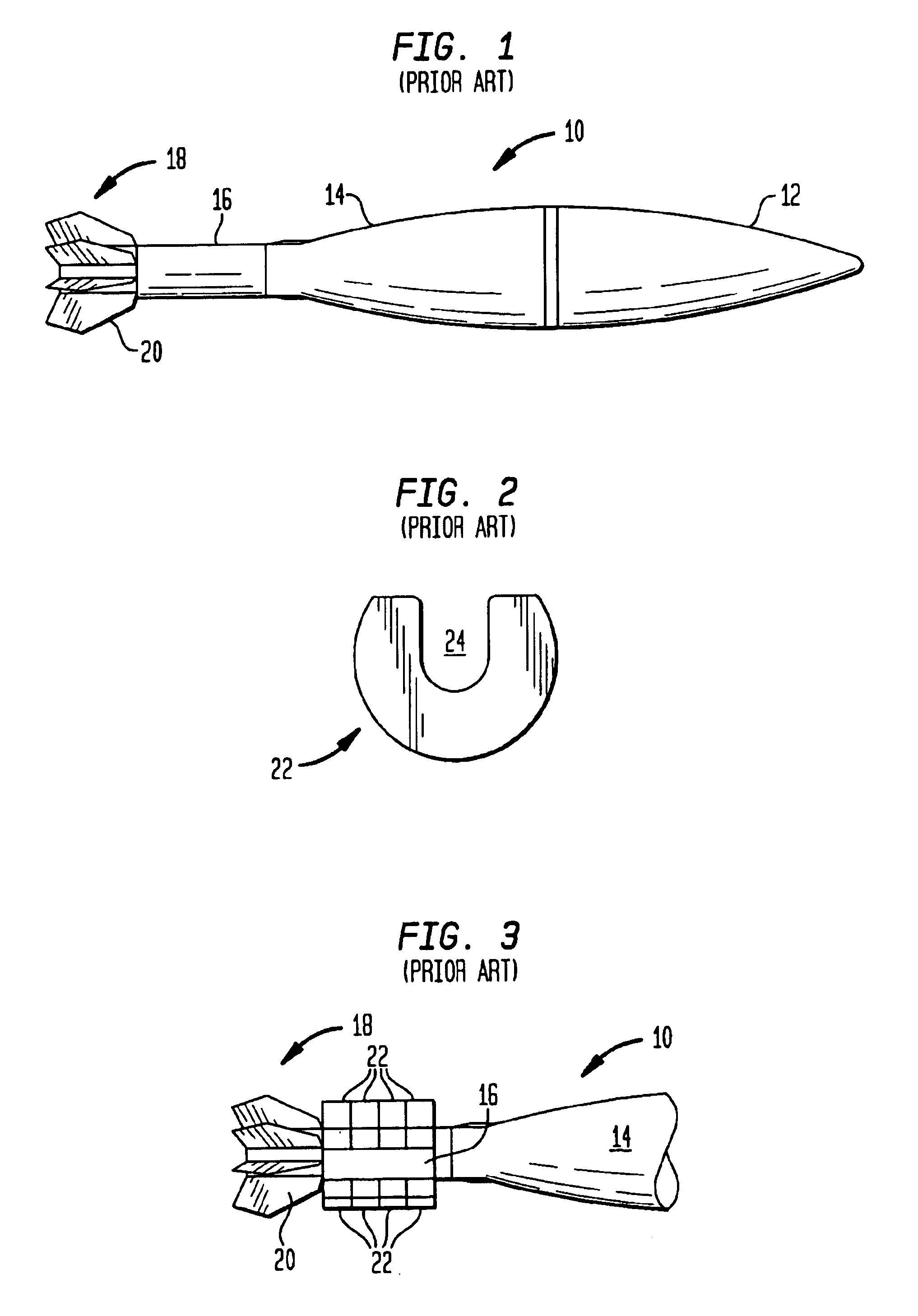
BACKGROUND OF INVENTIONThe invention relates in general to mortar shells and in particular to a protector for propelling charge increments mounted on a mortar shell.FIG. 1 is a side view of a known mortar shell 10. Mortar shell 10 includes a front portion 12, a middle portion 14, a tail tube 16 and a fin portion 18 comprising a plurality of fins 20. Middle portion 14 has a generally decreasing cross-section in the aft direction. Tail tube 16 is of substantially constant cross-section. FIG. 2 is an end view of a propelling charge increment 22. Increment 22 is generally horseshoe shaped with an opening 24. FIG. 3 is a side view of the aft portion of a mortar shell 10 with a plurality of propelling charge increments 22 mounted thereon. Increments 22 are mounted on the tail tube 16. The tail tube 16 fits into the opening 24 in each increment 22. Propelling charge increments 22 provide the propellant for launching the mortar shell 10 from a mortar gun tube.Prior to launch, there is a nee...

Claims


Application Information

Patent Timeline
IPC IPC(8): F42B30/00F42B30/12
CPCF42B30/12
Inventor KHANNA, VISHWADZURY, RICHARD CMILANO, KENNETHCHATTERJEE, TAPAN
Owner UNITED STATES OF AMERICA THE AS REPRESENTED BY THE SEC OF THE ARMY
Why Eureka
Try Eureka