Valve timing control system for internal combustion engine
Active Publication Date: 2005-01-04
HITACHI ASTEMO LTD
View PDF2 Cites 9 Cited by
Summary
Abstract
Description
Claims
Application Information
AI Technical Summary
This helps you quickly interpret patents by identifying the three key elements:
Problems solved by technology
Method used
Benefits of technology
Benefits of technology
It is, therefore, an object of the present invention to provide a valve timing control system for an internal combustion engine, which allows sure lock of the mounting angle between the driving rotator and the driven rotator at an angle position between the most-lagged-angle position and the most-advanced-angle position, and thus achievement of quick engine start.
Problems solved by technology
With the valve timing control system disclosed in JP-A 2002-155714, however, the fluttering speed of the camshaft with alternate torque is very high, so that at engine start, fluttering often makes the lock claw pass over the recess, leading to difficulty of surely engaging the lock claw in the recess at engine stop.
Thus, when the lock claw is not engaged in the recess at engine stop, subsequent engine start cannot be obtained quickly.
Method used
Image
Click on the blue label to locate the original text in one second.
Reading with bidirectional positioning of images and text.
Examples
first embodiment
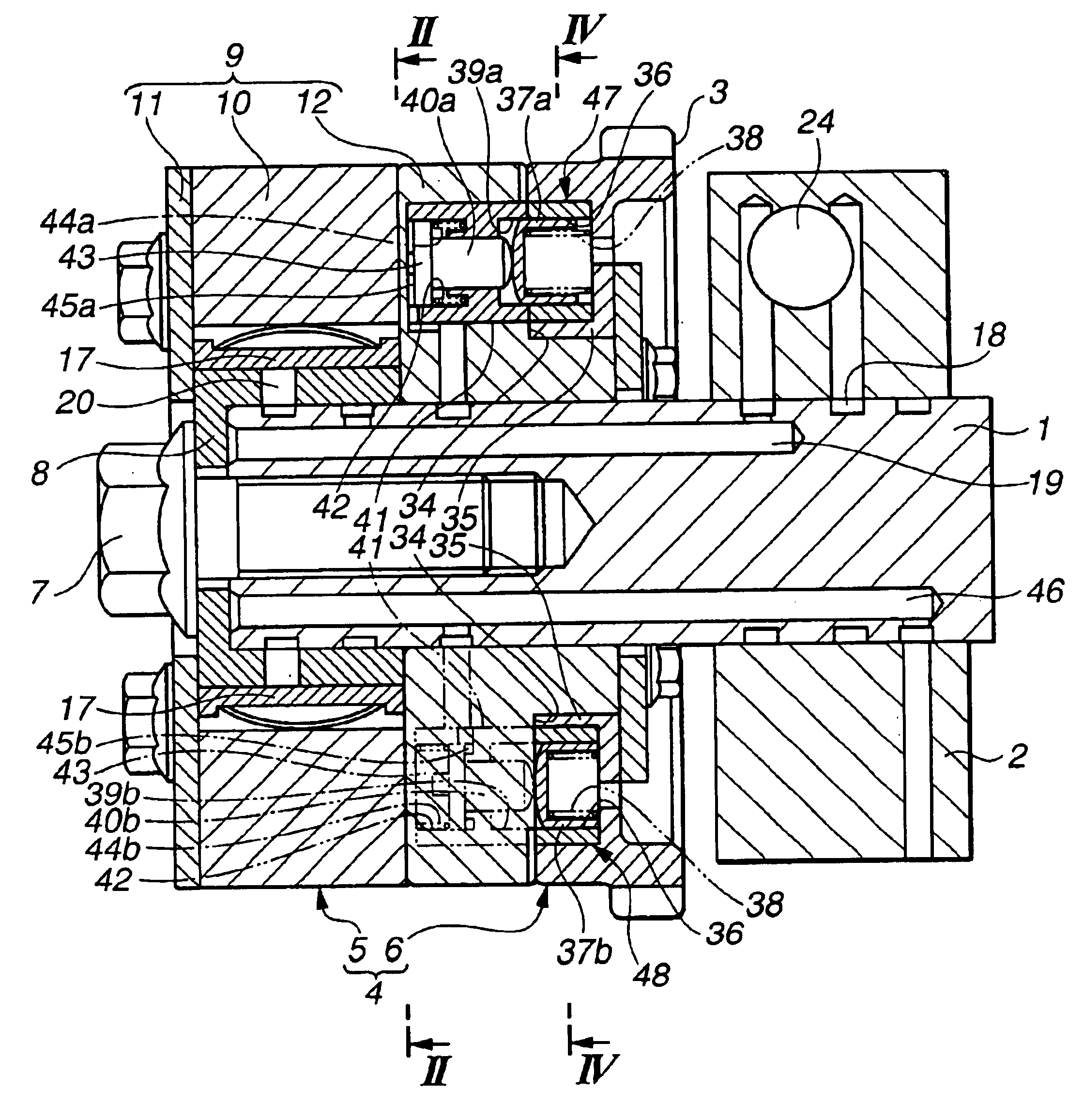
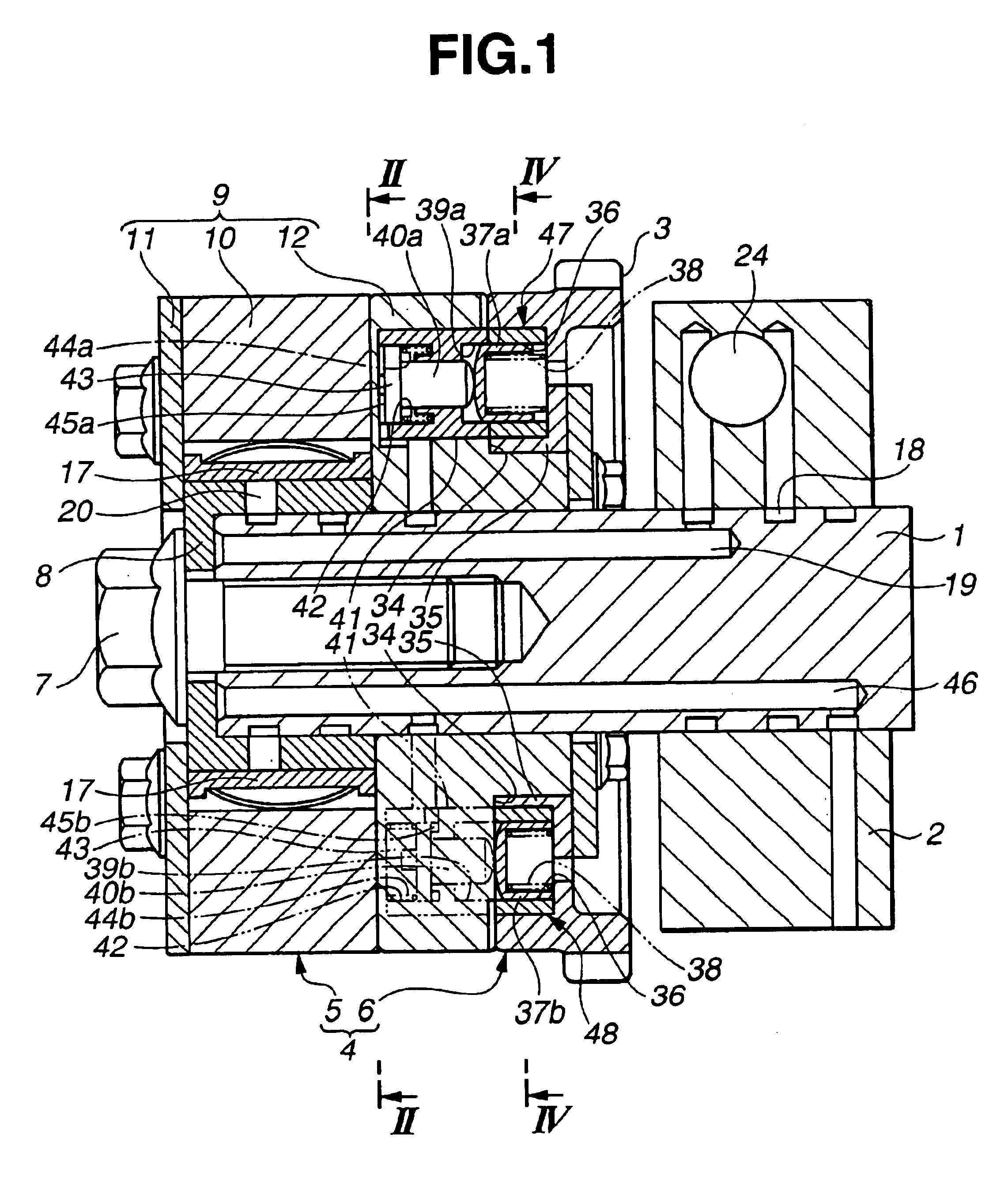
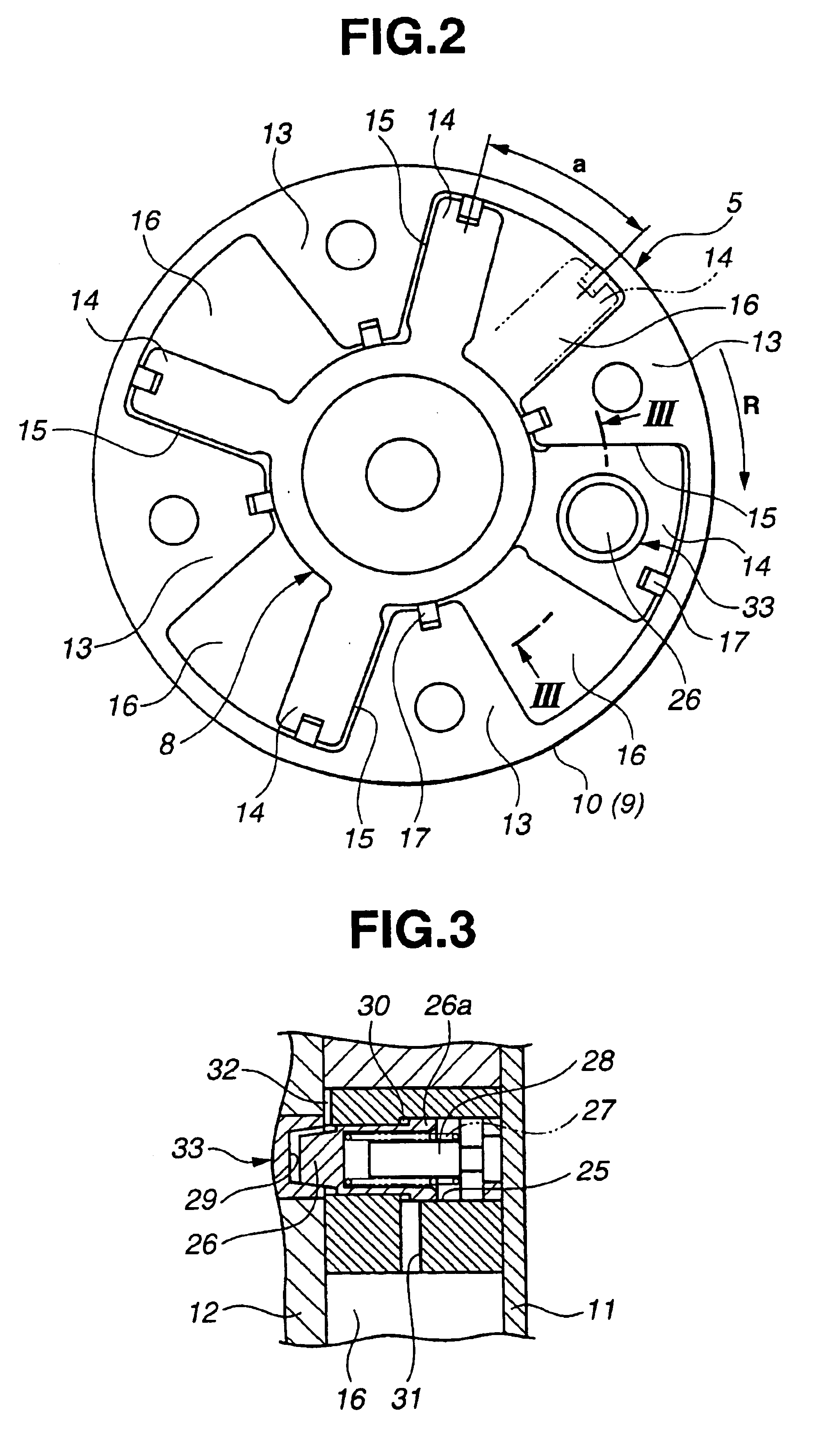
The valve timing control system comprises a chain sprocket or driving rotator 3 rotated by a crankshaft, not shown, of the engine through a timing chain or the like, camshaft 1 having chain sprocket 3 mounted at the front end to produce relative rotation as required, mounting-angle changing means or device 4 arranged between chain sprocket 3 and camshaft 1 for operating the mounting angle therebetween, and lock means or device for allowing lock of mounting-angle changing means 4 at a mounting-angle position suitable for engine start and comprising first and second lock mechanism 33, 47. In the first embodiment, the mounting-angle position suitable for engine start is set roughly at a middle position, i.e. position between the most-lagged-angle position and the most-advanced-angle position.
Mounting-angle changing means 4 comprises a first rotating mechanism 5 driven the hydraulic pressure and a second rotating mechanism 6 driven by alternate torque of camshaft 1. Referring to FIGS. 2...
second embodiment
In the second embodiment, therefore, second and third lock mechanisms 47,48 can provide quicker and surer lock of lock second rotating mechanism 6.
Referring to FIGS. 14 and 15, there is shown third embodiment of the present invention which is substantially the same as the first embodiment except lock pins 237a, 237b and lock openings 239a, 239b of second and third lock mechanisms 47, 48.
third embodiment
In the third embodiment, lock pins 237a, 237b and lock openings 239a, 239b are also formed with taper faces 50, 51. A taper center O′ of lock opening 239a, 239b when second rotating mechanism 6 is rotated up to one rotation restricting end is slightly offset in the direction of a restriction wall 34a of cavity 34 with respect to a taper center O′ of lock pin 237a, 237b.
In the third embodiment, an area of taper face 50 of lock opening 239a, 239b on the opposite side of restriction wall 34a produces a wedge action for pressing stopper protrusion 35 against restriction wall 34a during lock operation. Specifically, when lock pin 237a, 237b is pressed against the area of lock opening 239a, 239b on the opposite side of restriction wall 34a under biasing force of spring 38, lock pin 237a, 237b undergoes force from taper face 51 of lock opening 239a, 239b in the direction of making taper centers O, O′ coincide with each other, thus obtaining stopper protrusion 35 strongly pressed against r...
PUM
Abstract
A valve timingcontrol system includes a first device for changing a mounting angle between driving and driven rotators through relative rotation thereof and including first and second rotating mechanisms coupled to each other in series, and a second device for locking the first device at a mounting-angle position which is suitable for engine start and is set between a most-lagged-angle position and a most-advanced-angle position. The second device includes a first lock mechanism for locking the first rotating mechanism at one of the most-lagged-angle position and the most-advanced-angle position and a second lock mechanism for locking the second rotating mechanism at another position. The first and second rotating mechanisms are locked by the first and second lock mechanisms at opposite positions to maintain the mounting angle at the mounting-angle position suitable for engine start.
Description
BACKGROUND OF THE INVENTIONThe present invention relates to a valve timingcontrol system for controlling open / close timing of an intake valve and an exhaust valve of an internal combustion engine.The valve timingcontrol system comprises a driving rotator rotated by a crankshaft and a driven rotator integrated with a camshaft and mounted to the driving rotator so as to produce relative rotation as required. The mounting angle between the driving rotator and the driven rotator is appropriately controlled by mounting-angle changing means comprising a hydraulic actuator.Typically, the valve timing control system controls lift timing of the engine valve at engine start to the most-lagged-angle side or to the most-advanced-angle side. Recently, study is made to use timing more outward of lift timing at engine start, i.e. timing on the most-lagged-angle side or on the most-advanced-angle side, in accordance with vehicle cruising conditions. In this case, lift timing at engine start, i.e....
Claims
Application Information
Patent Timeline
Application Date:The date an application was filed.
Publication Date:The date a patent or application was officially published.
First Publication Date:The earliest publication date of a patent with the same application number.
Issue Date:Publication date of the patent grant document.
PCT Entry Date:The Entry date of PCT National Phase.
Estimated Expiry Date:The statutory expiry date of a patent right according to the Patent Law, and it is the longest term of protection that the patent right can achieve without the termination of the patent right due to other reasons(Term extension factor has been taken into account ).
Invalid Date:Actual expiry date is based on effective date or publication date of legal transaction data of invalid patent.

