
Automatic transmission and hydraulic control method therefor

Active Publication Date: 2012-11-29
JATCO LTD +1
View PDF2 Cites 13 Cited by
  • Summary
  • Abstract
  • Description
  • Claims
  • Application Information

AI Technical Summary

Benefits of technology

[0005]If the hydraulic pressure supplied to the starting frictional engagement element during the idle stop is controlled in advance to be a hydraulic pressure at which the starting frictional engagement element starts generating a transmission capacity, the transmission capacity of the starting frictional engagement element can be increased without delay and the vehicle can be quickly started in the case of a start request.
[0007]The present invention aims to obtain good starting performance even if a start request is made at a timing at which a hydraulic pressure supplied to a starting frictional engagement element drops by reducing a drop of the hydraulic pressure supplied to the starting frictional engagement element caused by the reverse rotation of an engine occurring immediately after the engine stops rotating.
[0010]According to these aspects, a drop of the hydraulic pressure supplied to the starting frictional engagement element caused by the reverse rotation of the engine can be reduced. In this way, a transmission capacity of the starting frictional engagement element can be increased and good starting performance can be obtained by quickly increasing the hydraulic pressure supplied to the starting frictional engagement element even if a start request is made at a timing at which the hydraulic pressure supplied to the starting frictional engagement element drops.

Problems solved by technology

However, there are cases where the engine slightly rotates in a reverse direction immediately after the rotation (forward rotation) thereof is stopped due to a force of compressed air in a combustion chamber to push back pistons and the weight of the pistons.

Method used


Image

  • Automatic transmission and hydraulic control method therefor
  • Automatic transmission and hydraulic control method therefor
  • Automatic transmission and hydraulic control method therefor

Examples


Embodiment Construction

[0019]In the following description, a “speed ratio” of a certain transmission mechanism is a value obtained by dividing an input rotation speed of this transmission mechanism by an output rotation speed thereof. Further, a “lowest speed ratio” means a maximum speed ratio of this transmission mechanism and a “highest speed ratio” means a minimum speed ratio thereof.

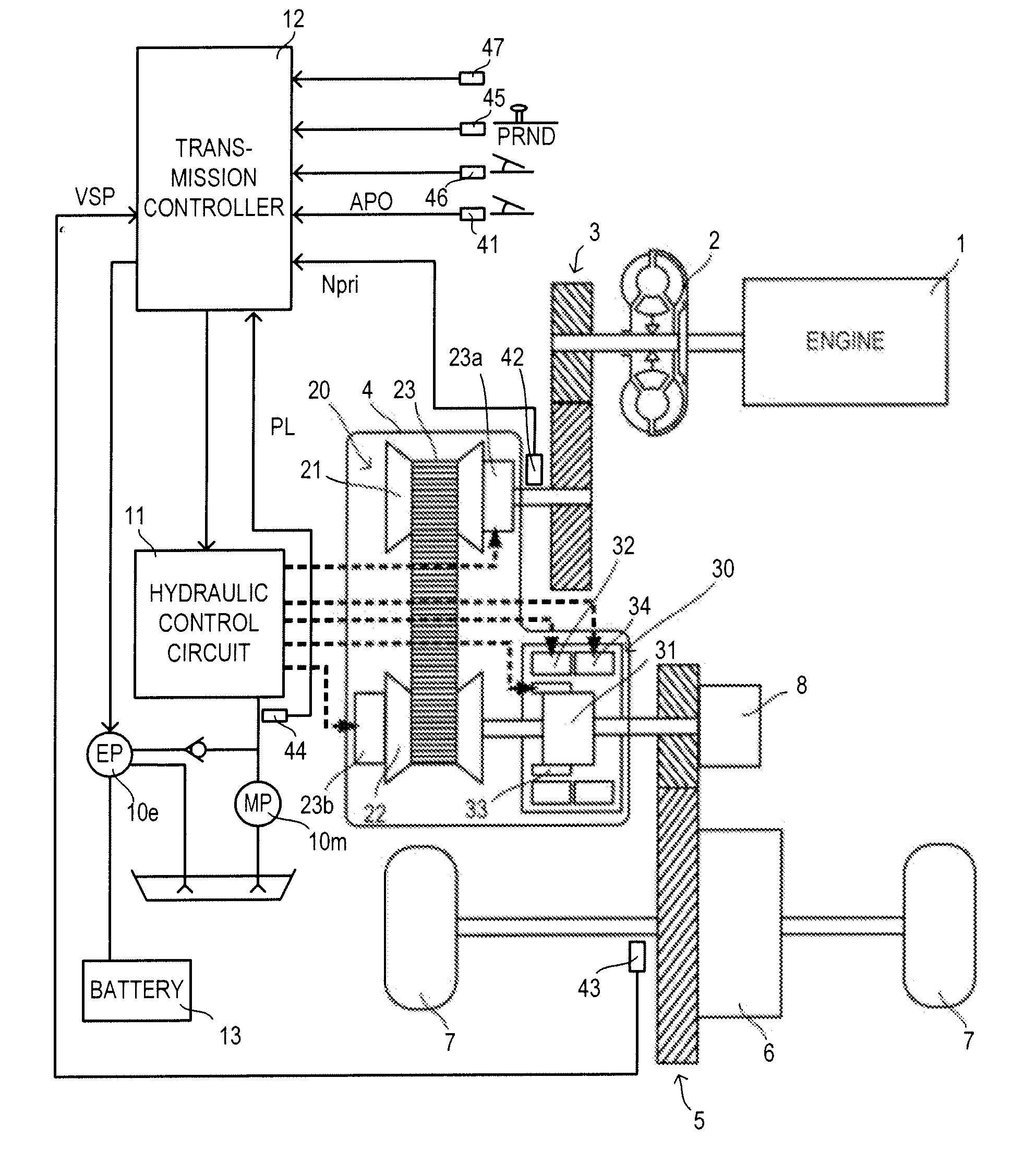
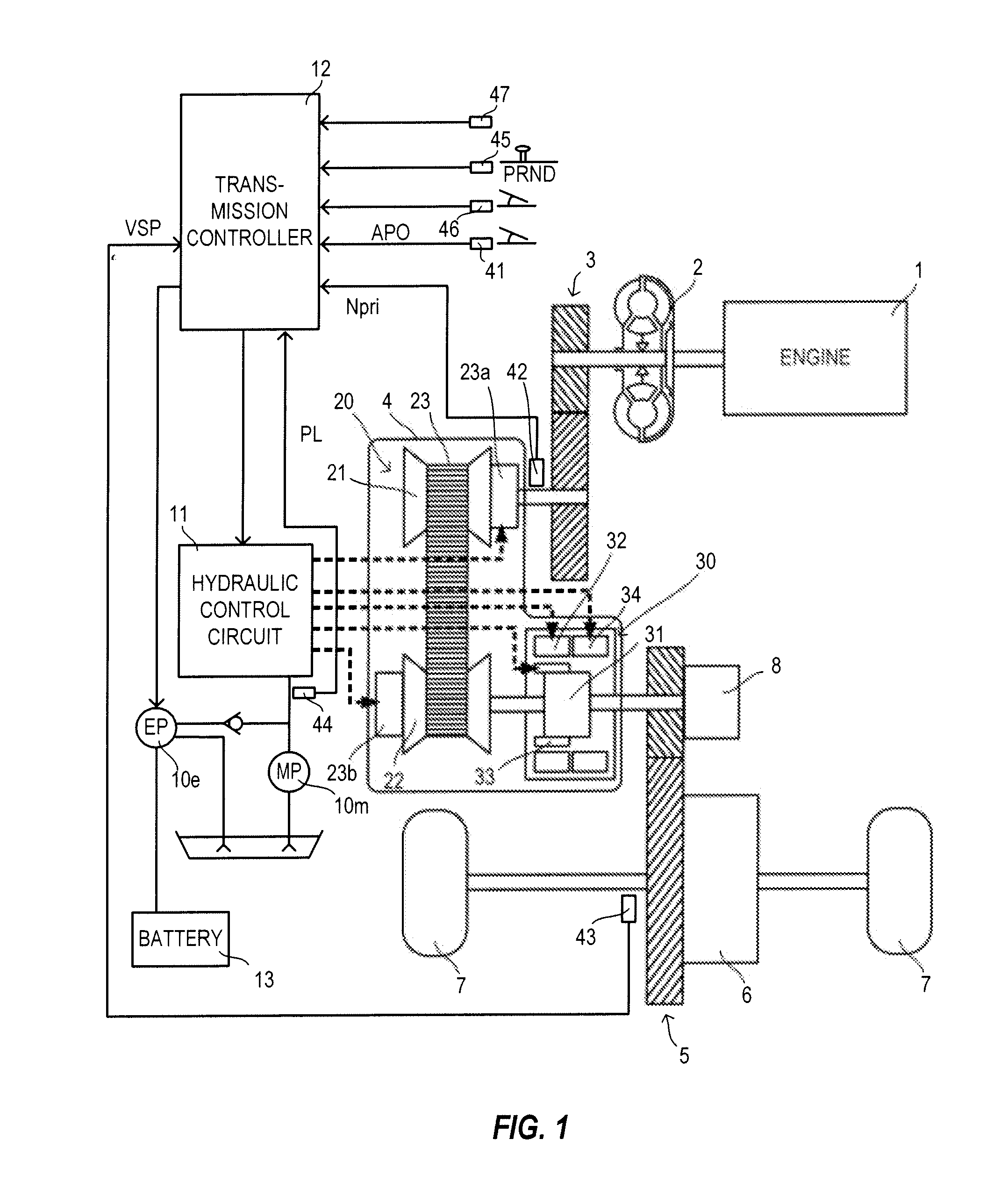
[0020]FIG. 1 is a schematic configuration diagram of a vehicle equipped with an automatic transmission according to an embodiment of the present embodiment. This vehicle includes an engine 1 as a drive source. Output rotation of the engine 1 is transmitted to drive wheels 7 via a torque converter 2 with a lock-up clutch, a first gear train 3, a continuously variable transmission (hereinafter, merely referred to as a “transmission 4”), a second gear train 5 and a final gear unit 6. The second gear train 5 includes a parking mechanism 8 for mechanically locking an output shaft of the transmission 4 in a vehicle parked state ...


PUM


Abstract

A transmission controller operates an electrical oil pump in a steady mode, in which an operating load of the electrical oil pump is set at a steady load, during an idle stop, but operates the electrical oil pump in a high-pressure mode, in which the operating load of the electrical oil pump is higher than the steady load, for a predetermined period when an engine stops rotating.

Description

TECHNICAL FIELD[0001]The present invention relates to an automatic transmission and particularly to an automatic transmission to be combined with an engine which performs an idle stop.BACKGROUND ART[0002]A technology for improving fuel economy and exhaust performance by automatically stopping (idle stop) an engine while a vehicle is stopped has been put to practical use.[0003]Since a mechanical oil pump cannot be driven by power of the engine while the engine is automatically stopped in a vehicle adopting this technology, a hydraulic pressure necessary at startup cannot be supplied from the mechanical oil pump to a starting frictional engagement element of the automatic transmission (brake, clutch to be engaged at startup) and the starting frictional engagement element is set in a non-engaged state. In this case, even if it is tried to start the vehicle in response to a start request, the engagement of the starting frictional engagement element is delayed, wherefore the vehicle cann...

Claims


Application Information

Patent Timeline
IPC IPC(8): B60W10/02
CPCF16H37/022F16H61/0031Y10T477/69395F16H2312/14Y10T477/753F16H61/66272F16H61/02F02D29/04F16H61/40
Inventor WAKU, KOUSUKEWAKAYAMA, HIDESHIMIYAZONO, MASAYUKITATEWAKI, KEICHITAKAHASHI, SEIICHIROTOHTA, YUZURUMATSUDA, TAKASHIMATSUMOTO, DAISUKE
Owner JATCO LTD
Learn More