Sealing system for an assembly

a sealing system and assembly technology, applied in the direction of engine sealing, sealing arrangements, machines/engines, etc., can solve the problem of not always ensuring the superficial engagement of the outer groove cheek along the entire length of the outer wall of the covering hood, and achieve the effect of reducing the difficulty of sealing to creep outward and strengthening the sealing action

Inactive Publication Date: 2005-01-04
ROBERT BOSCH GMBH
View PDF8 Cites 12 Cited by
  • Summary
  • Abstract
  • Description
  • Claims
  • Application Information

AI Technical Summary

Benefits of technology

The sealing device of the invention has the advantage over the prior art that because of the deformation of the luglike protrusion, variations between the two parts of the assembly can be compensated for in a simple way, while the wedge-shaped groove cheek makes it more difficult for the seal to creep outward. Thus on the one hand, by means of the luglike protrusion on the outer groove cheek, a secure closure of a gap between the parts of the assembly to prevent against the penetration of liquids or foreign bodies is achieved; on the other, by means of the wedge-shaped groove cheek, the seal is largely restrained in the groove, so that it can be subjected to a high pressure, which reinforces its sealing action. Nevertheless, a partial volume of the seal can overcome the wedge-shaped groove cheek to allow the two parts of the assembly to move toward one another far enough that the luglike protrusion impacts on its counterpart face. The rounded tip of the wedge-shaped groove cheek prevents the partial volume of the seal that has been positively displaced from the groove from being sheared off.

Problems solved by technology

However, because of variations in production or installation, a superficial engagement of the outer groove cheek along the entire length of the outer wall of the covering hood is not always assured.

Method used


Image

  • Sealing system for an assembly
  • Sealing system for an assembly

Examples


Embodiment Construction

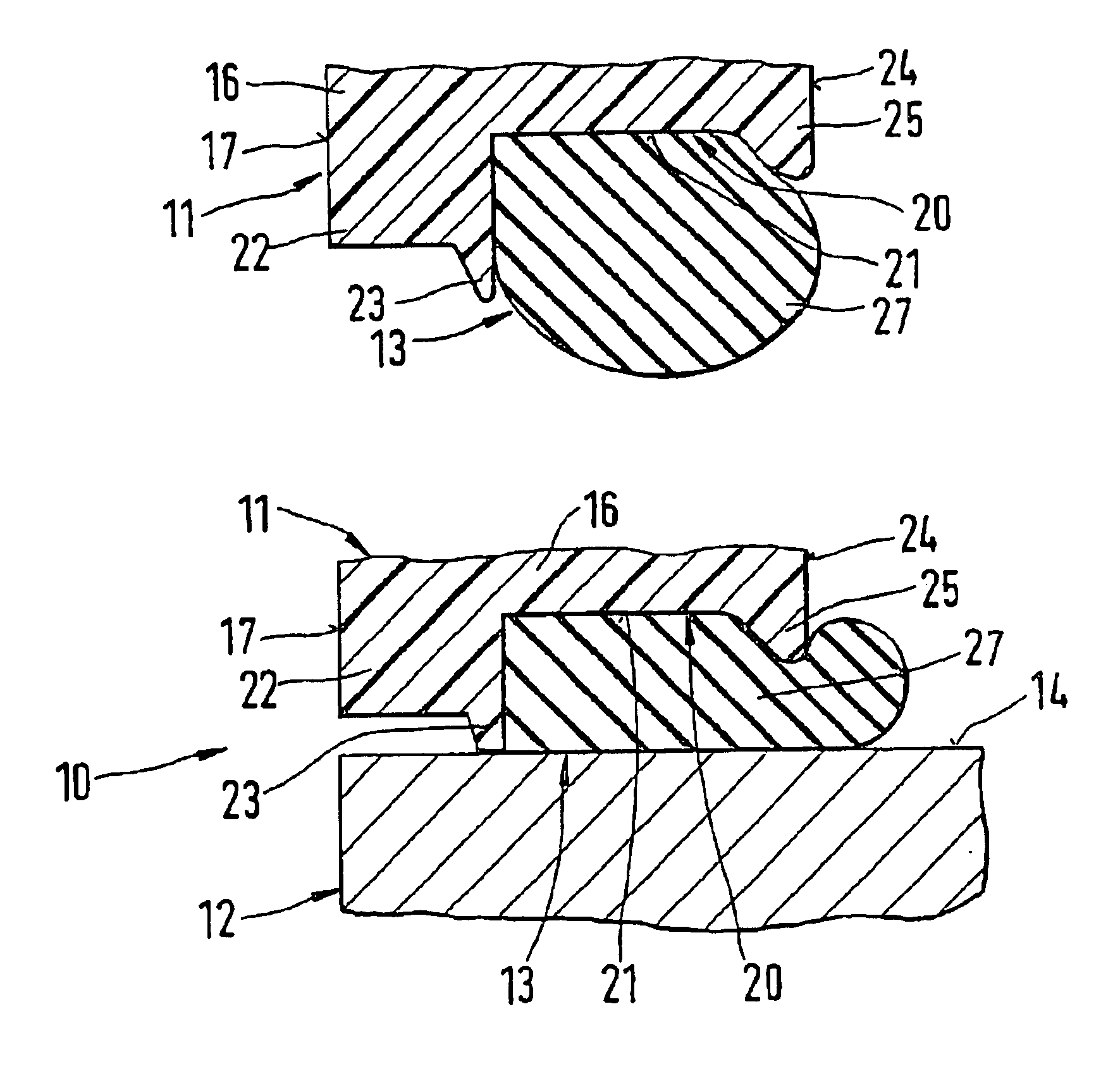
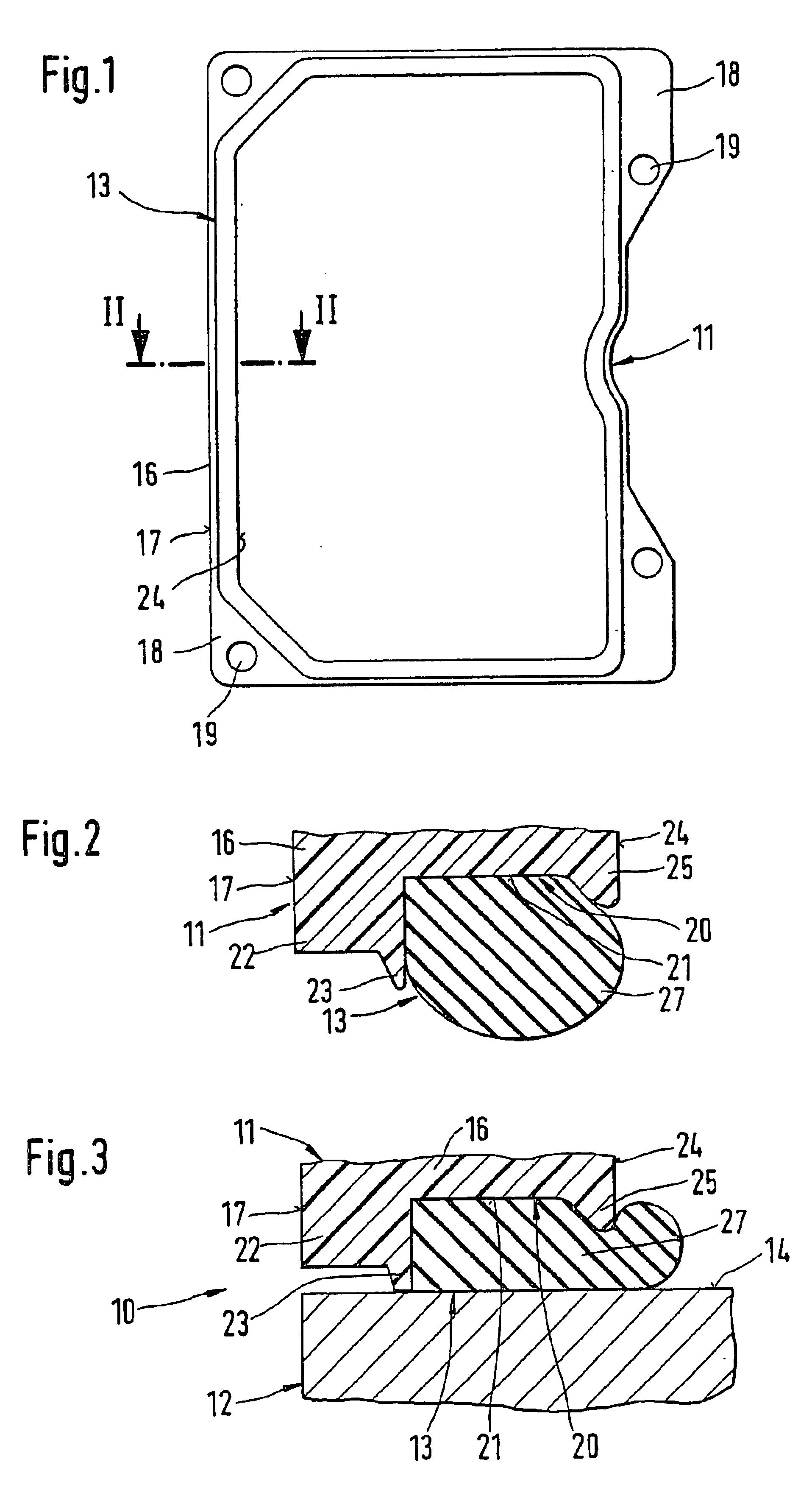
An assembly 10 shown only in part in FIG. 3 of the drawings comprises two parts 11 and 12, of which the part 11 embodied as a cap is provided with a sealing device 13. The other part 12 of the assembly 10 is a valve block, with a flat face 14 for engagement by the sealing device 13.

The part 11 shown in FIG. 1 before being mounted on part 12 has an encompassing wall 16, which is equipped on its outside 17 with flangelike extensions 18 as well as fastening holes 19 in the extensions for screwing part 11 to part 12, an operation not shown in the drawing. The sealing device 13 is embodied on the face end of this wall 16. The wall 16 has a groove 20, extending along the face end, which is open toward the part 12 and whose flat bottom 21 extends parallel to the face 14 of the part 12 (FIGS. 2 and 3). Toward the outside 17 of the wall 16, the groove 20 is bounded by a groove cheek 22. Immediately adjacent the groove 20, a luglike protrusion 23 of relatively slender cross section is formed ...


PUM


Abstract

One part of an assembly has one wall with a face-end groove in which a rubber-elastic seal is disposed. In the unstressed state, the seal protrudes past two groove cheeks of the groove. The groove cheek toward the outside is provided with a luglike protrusion while the groove cheek toward the inside has a lesser height than the groove cheek and is wedge-shaped in cross section. The protrusion of the outside groove cheek together with the seal forms a sealing device, whose action in the stressed state is based on the one hand on the plastic deformation of the protrusion on a face of a second part and on the other on the high pressure of the seal in the groove.

Description

BACKGROUND OF THE INVENTION1. Field of the InventionThe invention is directed to an improved sealing device for a hydraulic assembly.2. Description of the Prior ArtOne sealing device of the type with which this invention is concerned is already known (German Patent Disclosure DE 195 35 235 A1), in which a covering hood of a hydraulic assembly, on the free edge of its outer wall, has a groove extending all the way around, in which a separately injection-molded rubber-elastic seal rests with sealing lips. The groove is defined by groove cheeks of different heights: One groove cheek located toward the outside of the wall is higher than a groove cheek toward the inside. The outer groove cheek superficially engages a flat face end of a valve block of the hydraulic assembly. The inner groove cheek, with its flat end face, engages the seal and maintains the contact of this seal with the valve block. While the rubber-elastic seal statically seals off the interior of the covering hood, the o...

Claims


Application Information

Patent Timeline
Patent Type & Authority Patents(United States)
IPC IPC(8): F16J15/06F16J15/10
CPCF16J15/062F16J15/06
Inventor FLUCK, TOBIASSPIES, PHILIPP
Owner ROBERT BOSCH GMBH
Why Eureka
Try Eureka