Sealing system for an assembly

Inactive Publication Date: 2004-02-26
ROBERT BOSCH GMBH
View PDF7 Cites 10 Cited by
  • Summary
  • Abstract
  • Description
  • Claims
  • Application Information

AI Technical Summary

Problems solved by technology

However, because of variations in production or installation, a superficial engagement of the outer

Method used


Image

  • Sealing system for an assembly
  • Sealing system for an assembly

Examples


Embodiment Construction

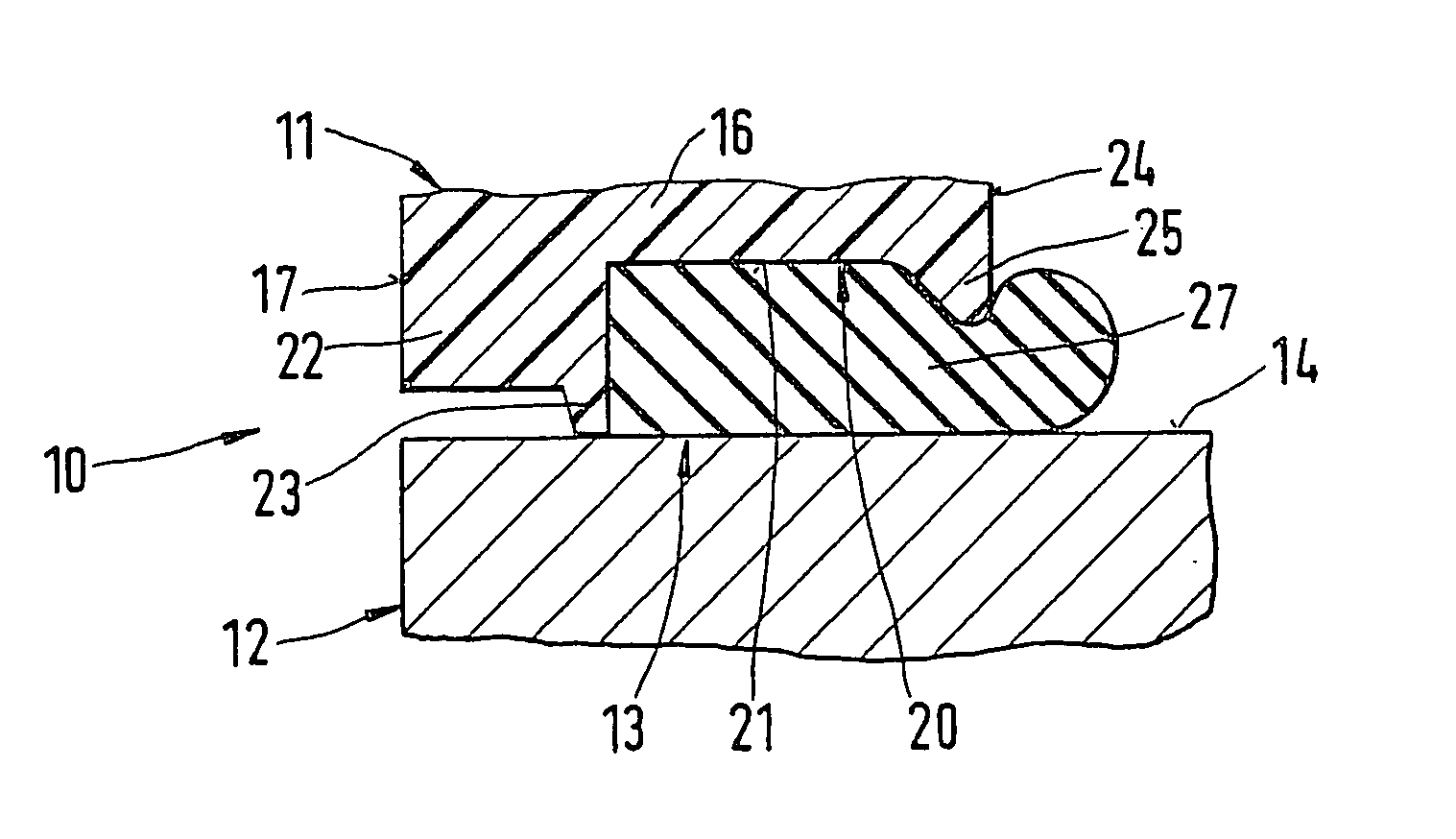
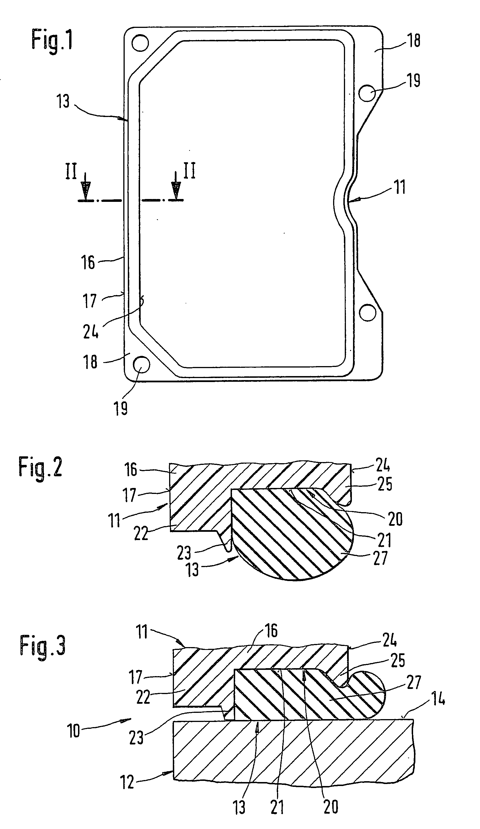
[0009] An assembly 10 shown only in part in FIG. 3 of the drawing comprises two parts 11 and 12, of which the part 11 embodied as a cap is provided with a sealing device 13. The other part 12 of the assembly 10 is a valve block, with a flat face 14 for engagement by the sealing device 13.

[0010] The part 11 shown in FIG. 1 before being mounted on part 12 has an encompassing wall 16, which is equipped on its outside 17 with flangelike extensions 18 as well as fastening holes 19 in the extensions for screwing part 11 to part 12, an operation not shown in the drawing. The sealing device 13 is embodied on the face end of this wall 16. The wall 16 has a groove 20, extending along the face end, which is open toward the part 12 and whose flat bottom 21 extends parallel to the face 14 of the part 12 (FIGS. 2 and 3). Toward the outside 17 of the wall 16, the groove 20 is bounded by a groove cheek 22. Immediately adjacent the groove 20, a luglike protrusion 23 of relatively slender cross secti...


PUM


Abstract

One part 11 of an assembly 10 has one wall 16 with a face-end groove 20, in which a rubber-elastic seal 27 is disposed. In the unstressed state, the seal 27 protrudes past two groove cheeks 22 and 25 of the groove 20. The groove cheek 22 toward the outside is provided with a luglike protrusion 23, while the groove cheek 25 toward the inside has a lesser height than the groove cheek 22 and is wedge-shaped in cross section. The protrusion 23 of the groove cheek 22 together with the seal 27 forms a sealing device, whose action in the stressed state is based on the one hand on the plastic deformation of the protrusion 23 on a face 14 of a second part 12 and on the other on the high pressure of the seal 27 in the groove 20.

Description

PRIOR ART[0001] The invention is based on a sealing device as generically defined by the preamble to claim 1.[0002] One such sealing device is already known (German Patent Disclosure DE 195 35 235 A1), in which a covering hood of a hydraulic assembly, on the free edge of its outer wall, has a groove extending all the way around, in which a separately injection-molded rubber-elastic seal rests with sealing lips. The groove is defined by groove cheeks of different heights: One groove cheek located toward the outside of the wall is higher than a groove cheek toward the inside. The outer groove cheek superficially engages a flat face end of a valve block of the hydraulic assembly. The inner groove cheek, with its flat end face, engages the seal and maintains the contact of this seal with the valve block. While the rubber-elastic seal statically seals off the interior of the covering hood, the outer groove cheek is intended to prevent a jet of steam of water, for instance, from a high-pr...

Claims


Application Information

Patent Timeline
IPC IPC(8): F16J15/06F16J15/10
CPCF16J15/062F16J15/06
Inventor FLUCK, TOBIASSPIES, PHILIPP
Owner ROBERT BOSCH GMBH
Why Eureka
Try Eureka