Equipment-mounting wire harness

a wire harness and equipment technology, applied in the direction of insulated conductors, cables, coupling device connections, etc., can solve the problems of increasing the number of shield shells, time and labor required for mounting the shield shells, and liquid (for example, lubricating oil) inside the shield shells that leak to the exterior, so as to reduce the number of components and secure the effect of sealing ability

Inactive Publication Date: 2005-01-04
AUTONETWORKS TECH LTD +2
View PDF6 Cites 33 Cited by
  • Summary
  • Abstract
  • Description
  • Claims
  • Application Information

AI Technical Summary

Benefits of technology

This invention has been made under the above circumstances, and an object of the invention is to reduce the number of component parts and also to secure a sealing ability.

Problems solved by technology

Thus, in the conventional structure, although there are used the plurality of shielded wires, the separate shield shells are required respectively for the shielded wires, and therefore there has been encountered a disadvantage that the number of the shield shells, as well as the time and labor required for mounting the shield shells, increases.
Therefore, there is a fear that a liquid (for example, lubricating oil) within the shield casing leaks to the exterior of the shield casing through gaps between metal wire elements forming the shielded wire.

Method used


Image

  • Equipment-mounting wire harness
  • Equipment-mounting wire harness
  • Equipment-mounting wire harness

Examples


first embodiment

[First Embodiment]

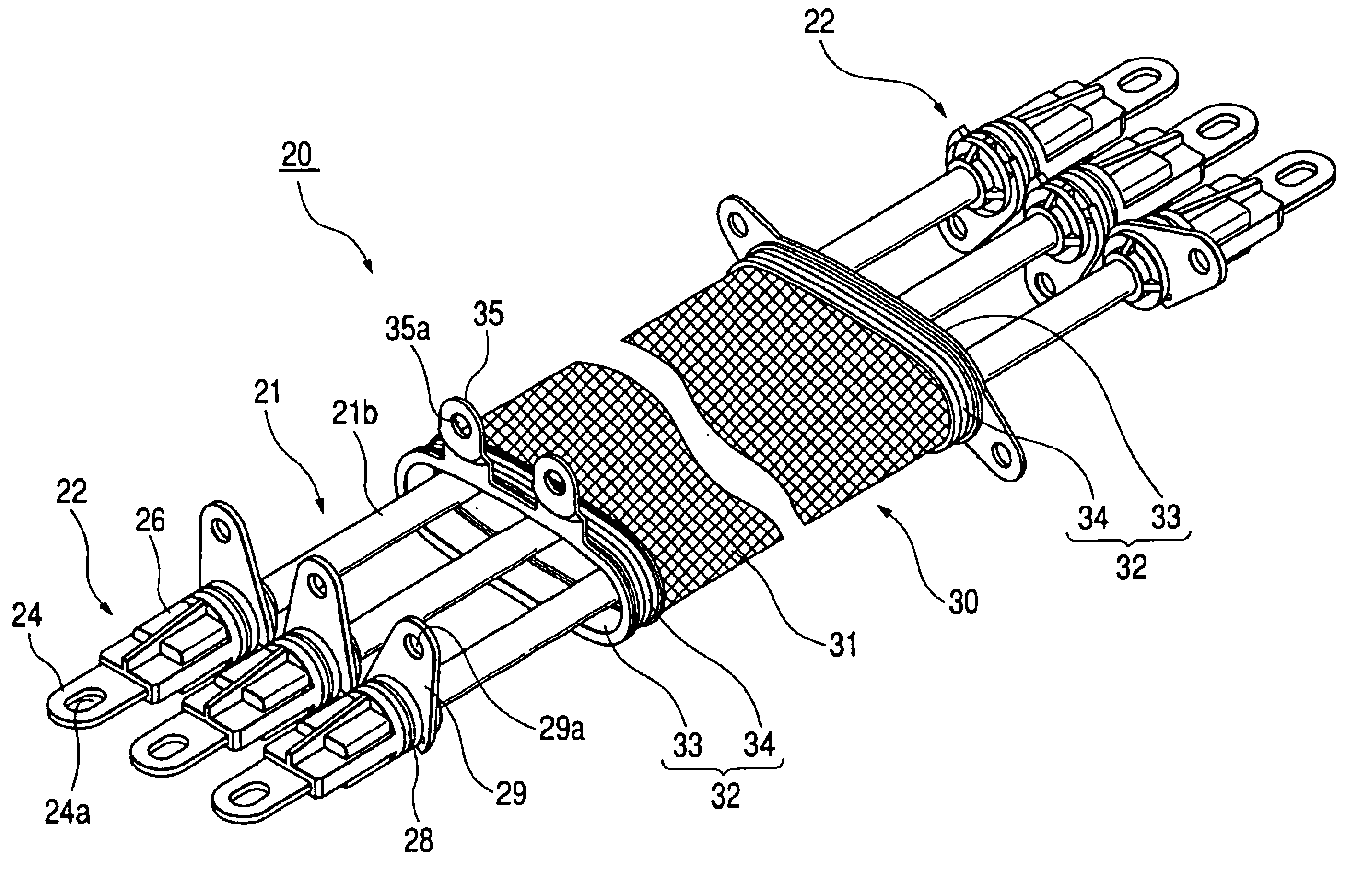
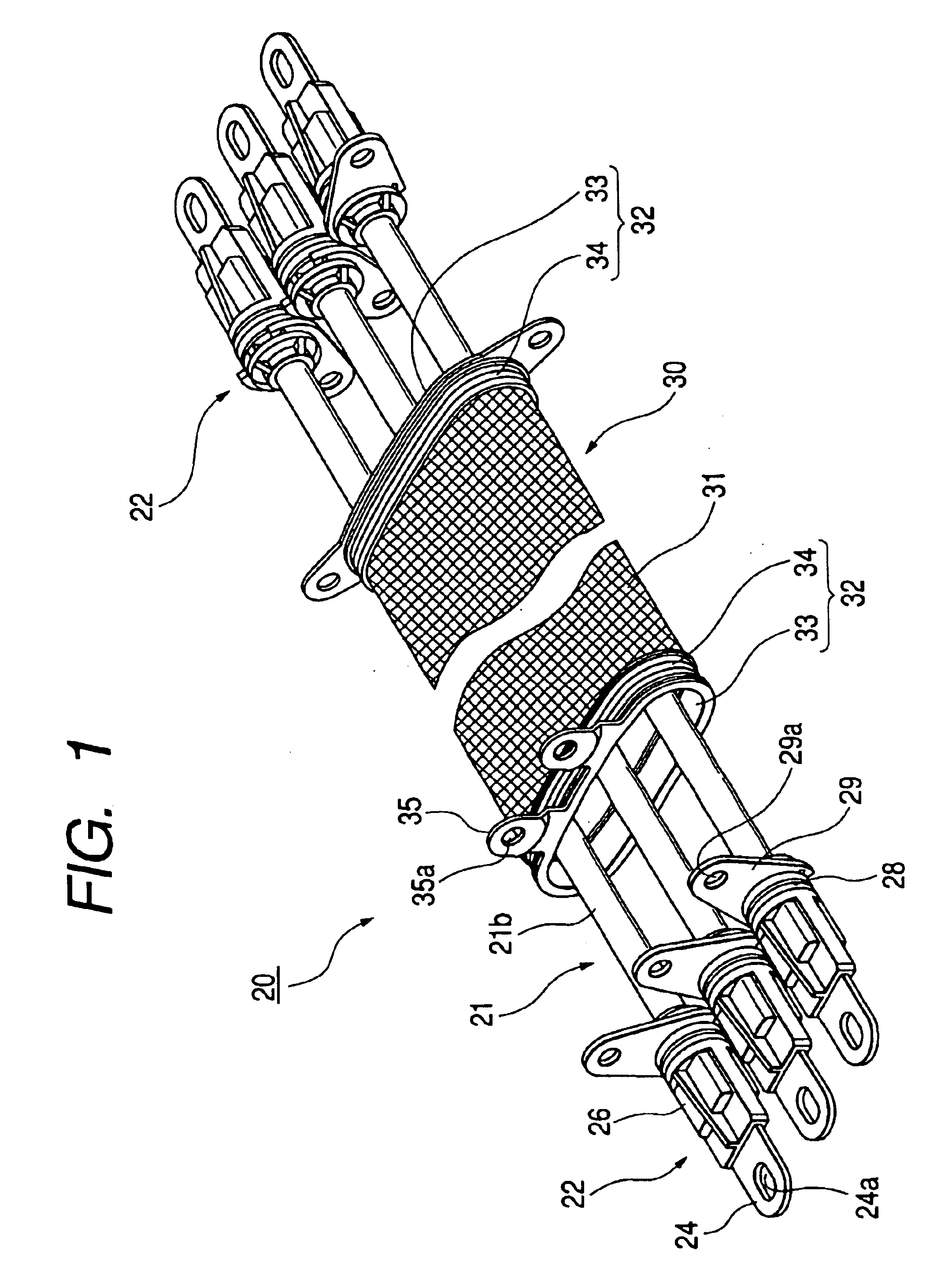
A first embodiment of the present invention will now be described with reference to FIGS. 1 to 4.

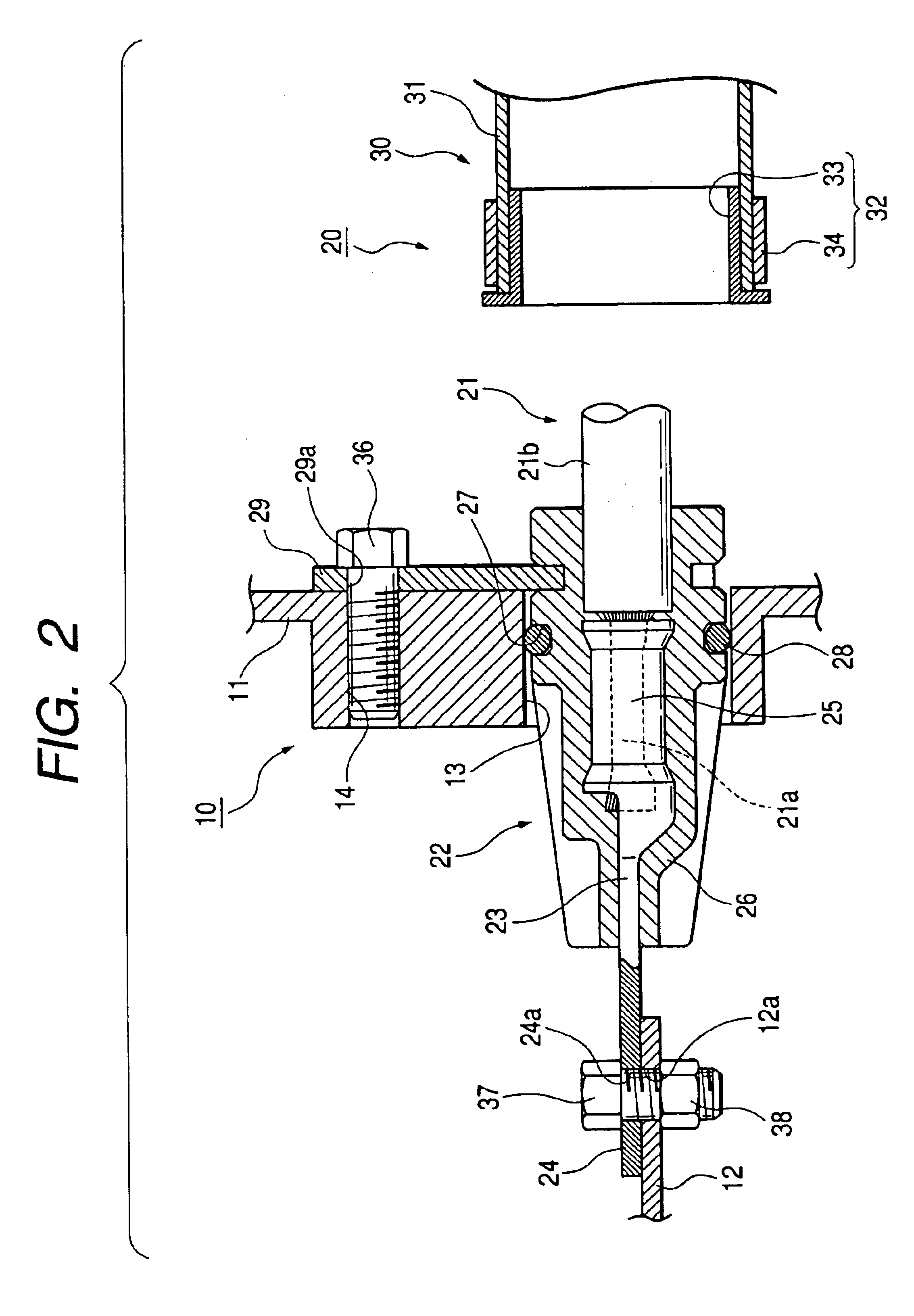
First, an equipment 10, to which an equipment-mounting wire harness 20 (herein after referred to merely as “wire harness 20”) of this embodiment is to be connected, will be described. The equipment 10 includes a shield casing 11 within which a plurality of equipment-side terminals 12 are received, and a plurality of mounting holes 13 of a round shape, corresponding respectively to the equipment-side terminals 12, are formed in the shield casing 11. Internal thread holes 14, corresponding respectively to the mounting holes 13, are formed in the shield casing 11, and internal thread holes 15 for mounting a shield shell 32 are formed in the shield casing 11.

The wire harness 20 of this embodiment comprises a plurality of wires 21, connectors 22 fixedly secured respectively to end portions of the wires 21, and collective shielding means 30. The wire 21 is of the non-shielded...

second embodiment

[Second Embodiment]

Next, a second embodiment of the present invention will be described with reference to FIG. 5.

This second embodiment differs from the first embodiment in that a connector 40 has an L-shape. The other construction is the same as that of the first embodiment, and therefore identical portions will be designated by identical reference numerals, respectively, and explanation of the structure, operation and effects thereof will be omitted.

In this embodiment, the connector 40 comprises an L-shaped metal terminal 41, and a connector body 44 resin-molded to embrace the metal terminal 41. The separate connector bodies 44 are molded to respectively embrace the metal terminals 41 fixedly secured respectively to wires 21.

A horizontal front end portion of the metal terminal 41 is formed into a terminal connection portion 42, and an open barrel-like wire connection portion 43 is formed at a rear end portion of the metal terminal 41 which extends downwardly (in a direction perpen...


PUM

PropertyMeasurementUnit
shapeaaaaaaaaaa
electrically-conductiveaaaaaaaaaa
flexibleaaaaaaaaaa

Abstract

An equipment-mounting wire harness for mounting on equipment, which includes a shield casing for accommodating a plurality of equipment-side terminals. The equipment-mounting wire harness includes a plurality of wires and metal terminals. Each of the metal terminals includes a terminal connection portion for connecting to the equipment-side terminal and a wire connection portion for connecting to the wire. The wire harness further includes a connector body, a seal ring, a tubular shield member, a tubular shield member and a shield shell. The connector body can be fitted into the mounting hole and is molded to embrace the wire connection portions. The seal ring seals a gap between the connector body and an inner surface of a mounting hole of the shield casing. The tubular shield member collectively covers the wires in a surrounding manner. The shield shell secures an end portion of the shield member to the shield casing.

Description

BACKGROUND OF THE INVENTION1. Field of the InventionThis invention relates to a wire harness for mounting on an equipment.2. Background ArtJP-A-11-26093 discloses a conventional structure for connecting a plurality of shielded wires to an equipment such as an inverter device in an electric car. In this structure, mounting holes are formed in an electrically-conductive shield casing, and equipment-side terminals, provided within the shield casing, are disposed immediately adjacent respectively to these mounting holes in opposed relation thereto, and wire-side terminals, fixedly secured respectively to end portions of the shielded wires, are set respectively in the mounting holes, and are connected respectively to the equipment-side terminals, and an end portion of a shield layer of each of the shielded wires is connected to the shield casing. Generally, a tubular member (called a braided wire), which is so flexible as to be deformed, is used as a shield layer of a shielded wire, and ...

Claims


Application Information

Patent Timeline
Patent Type & Authority Patents(United States)
IPC IPC(8): H01R11/01H01R13/52H01R13/74H01R4/28H01R4/30H01R4/70H01B7/00H01R9/03H02G1/14H02G3/04H02G15/08
CPCH01R9/032H01R13/5202H01R11/01H01R4/30H01R4/70H01R2201/26H01R13/748H01R13/65912
Inventor MIYAZAKI, SHOAIHARA, HIROSHITSUKASHIMA, HIROYUKI
Owner AUTONETWORKS TECH LTD
Why Eureka
Try Eureka