
Knife sheath

a blade and sheath technology, applied in the field of blade sheaths, can solve the problems of blades not fitting properly, difficult insertion and retraction of blades into known sheaths, and blades being easily stuck or grated against a surfa

Inactive Publication Date: 2005-01-11
INNOVATIVE MARINE PRODS
View PDF16 Cites 9 Cited by
  • Summary
  • Abstract
  • Description
  • Claims
  • Application Information

AI Technical Summary

Benefits of technology

"The present invention provides a knife sheath with a hollow body for receiving a knife blade. The sheath has a suspension strap attached to its proximal end, which forms a loop. The strap has a second longitudinal axis that intersects with the first longitudinal axis of the sheath body at a small angle. The invention also provides a blade carrying tool with a casing and a carrying member that are not aligned. The technical effects of the invention include improved comfort, secure carrying of the knife blade, and easy access to the blade."

Problems solved by technology

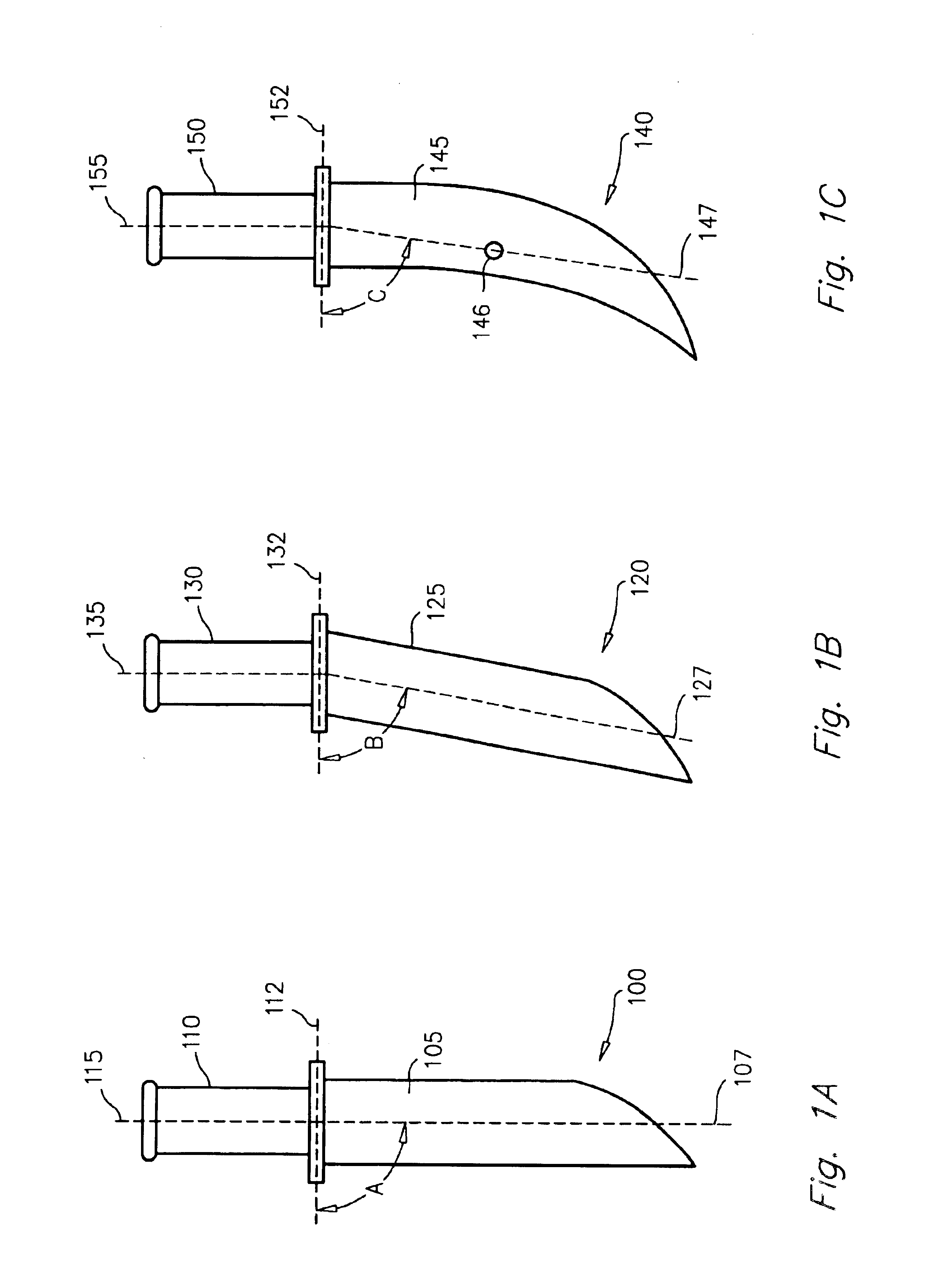
A problem arises in these criterion with regard to knives having various angles or curvature.
First, the blades do not fit properly.
Second, the insertion and retraction of a blade into known sheaths is difficult, with the blade being easily stuck or grated against a surface.
Furthermore, as such knives are primarily intended for kitchen use, little attention has been paid to the needs of sportsmen who may wish to carry such a knife in an easily accessed manner.
The insertion or retraction of curved or angled blades into known straight sheaths creates added problems of friction, misalignment, and awkward movement.

Method used


Image

  • Knife sheath
  • Knife sheath
  • Knife sheath

Examples


Embodiment Construction

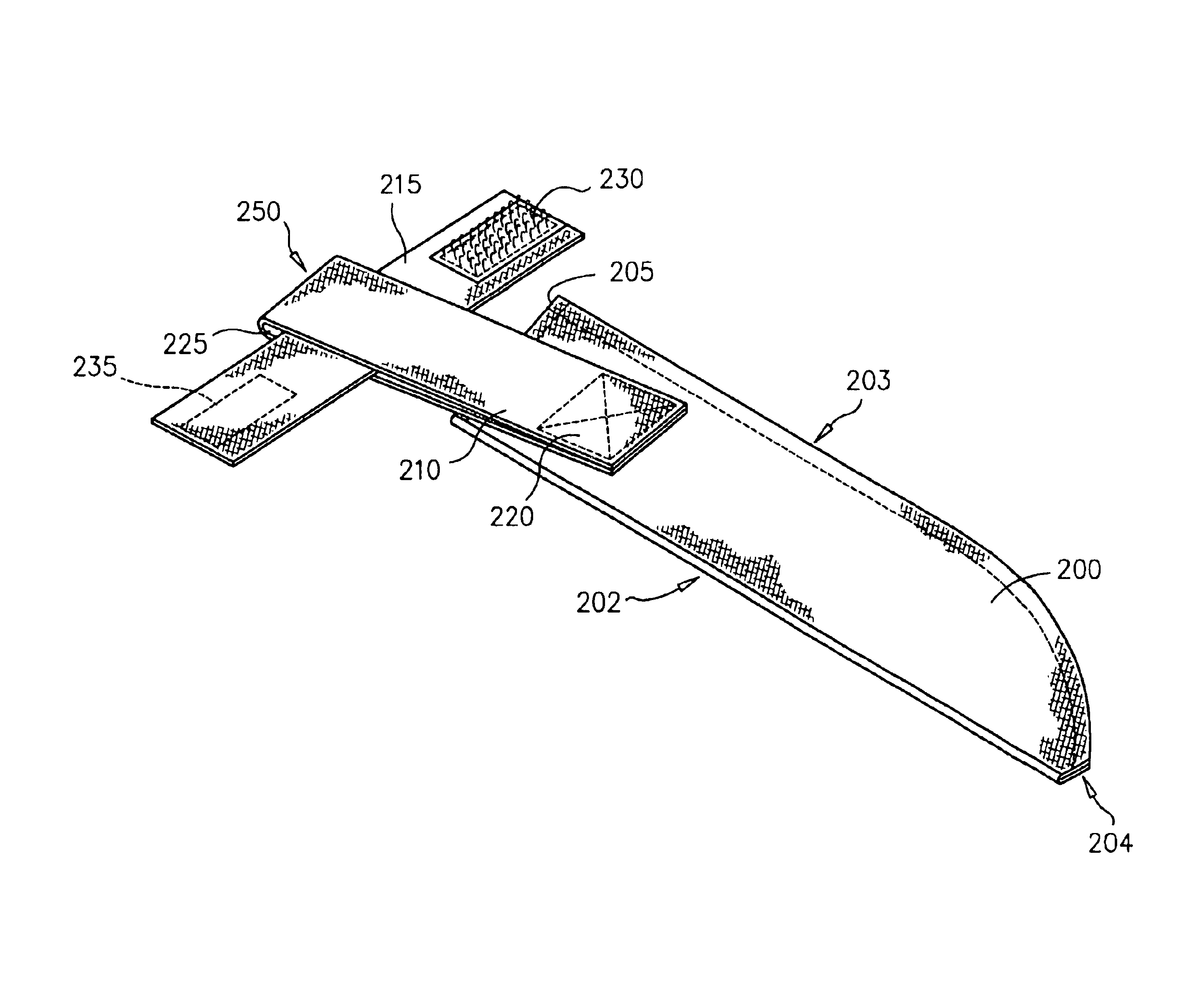
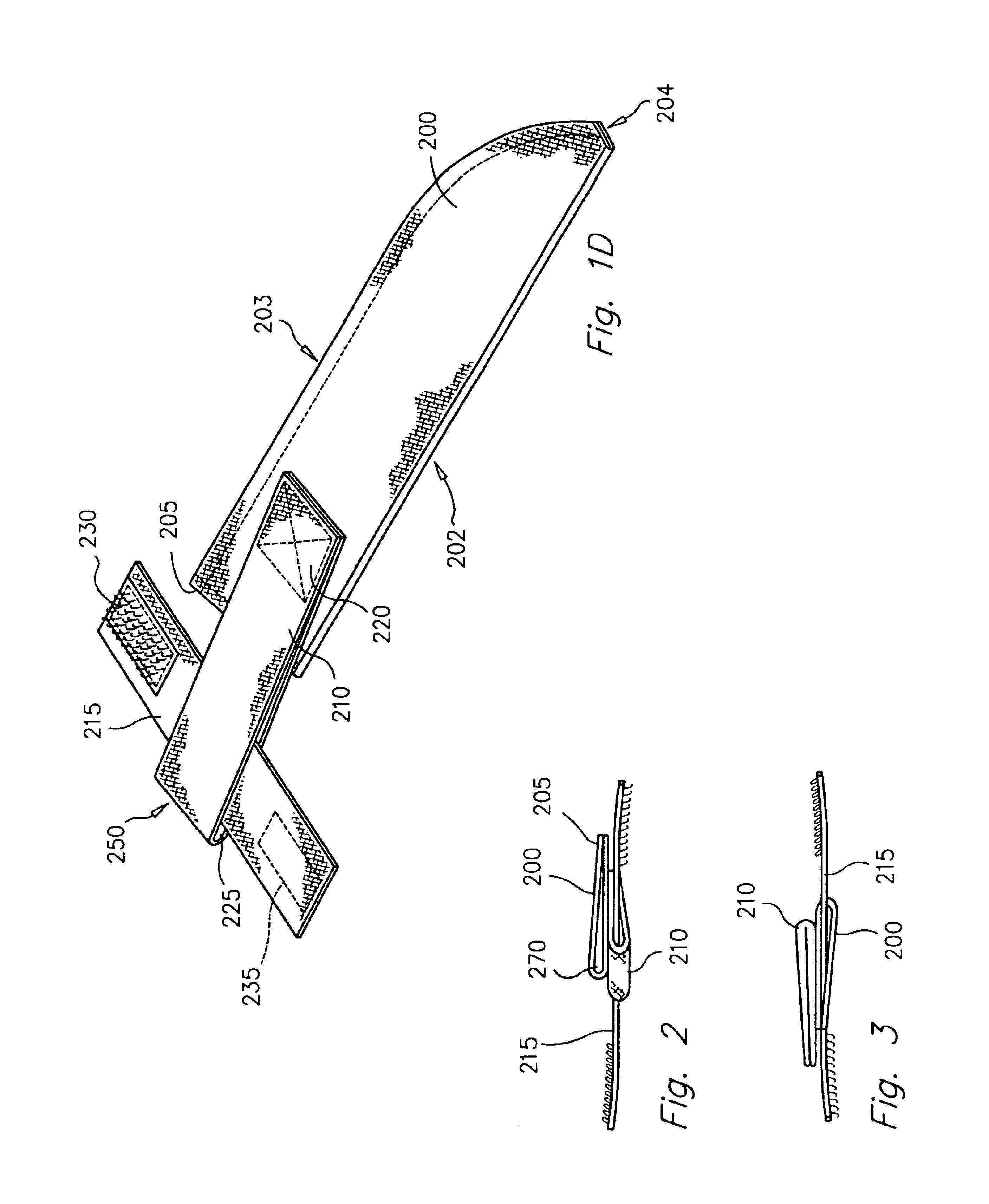
FIG. 1D illustrates a knife sheath or covering in accordance with the present invention. The sheath includes a sheath body or scabbard 200, having a front edge 202, back edge 203, tip 204, and top edge 205. The sheath also includes a suspension or carrying strap 210 and securing member 215. In the illustrated embodiment, the sheath body 200 is a scabbard or casing made of a robust material such as Cordura nylon which is shaped to provide a particular profile when folded and stitched as shown. The suspension strap 210, also made of Cordura nylon, includes a strip of material formed into a loop, stitched together at one end, and secured to the sheath body 200 at an attachment point 220. Cordura nylon is but one of many possible materials suitable for use with the present invention. It is appreciated that several other materials may also be used without deviating from the principles of the present invention, such as plastic or polymer, metal or metal alloy, natural or synthetic fibers ...


PUM


Abstract

A sheath for carrying a knife or blade is disclosed. The sheath includes a scabbard attached to a carrying strap forming a loop through which a carrying junction such as a belt may be passed. The axis of the loop is generally aligned with a transverse axis perpendicular to an axis of gravity. The length of the scabbard includes a longitudinal axis generally angled with respect to the axis of gravity. The mouth of the scabbard is further angled with regard to the transverse axis. Each of the foregoing alignments allows a user to more easily and efficiently insert and remove a blade into the scabbard while carrying the sheath. The sheath is also provided with an inner shell disposed inside the scabbard, the inner shell having a plurality of lengthwise linear ridges for gripping the blade inside the shell.

Description

STATEMENT REGARDING FEDERALLY SPONSORED RESEARCH OR DEVELOPMENTn / aFIELD OF THE INVENTIONThe present invention relates to a knife sheath, and more particularly to a sheath for a curved or angled knife.BACKGROUND OF THE INVENTIONKnives require sheaths for varying purposes. A proper sheath requires several attrubutes. Generally, an ideal sheath conforms to the contours of the knife, and incorporates the aesthetic design and quality of the knife. Furthermore, a sheath needs to properly enclose the blade to keep it safe from outside contact or for carrying and storage. Finally, a sheath must allow for easy and reliable insertion and retraction of the knife.A problem arises in these criterion with regard to knives having various angles or curvature. Knives having blade portions disposed at an angle with respect to each other, or knives having curved blades are known as shown in FIGS. A-C. FIG. A shows a knife 100 having blade 105 with a longitudinal axis 107, and a handle 110 having a tra...

Claims


Application Information

Patent Timeline
Patent Type & Authority Patents(United States)
IPC IPC(8): B26B29/02B26B29/00F41B13/00F41B13/04
CPCA45F5/021F41B13/04B26B29/025
Inventor ABERMAN, HOWARD S.
Owner INNOVATIVE MARINE PRODS
Learn More